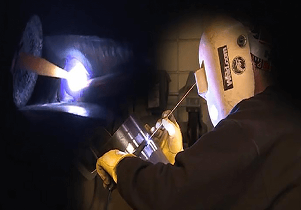
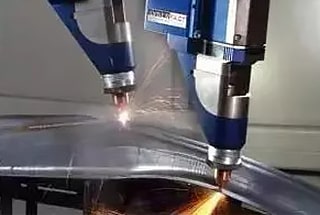
Ever wondered how welders achieve perfect joints in challenging positions? 6GR welding is a specialized technique for welding pipelines with an obstacle ring at a 45° angle, crucial for ensuring structural integrity in various industries. This article unpacks the complexities and precise steps of 6GR welding, from pipe assembly to overcoming technical difficulties in backing welds. Dive in to discover how mastering these techniques can elevate the quality and reliability of your welding projects.
The 6GR welding of the pipe involves fixing the pipe with an obstacle ring at a 45° incline angle.
The axis of the pipe forms a 45° angle with the horizontal plane, and its position is fixed and unchanging.
The obstacle ring’s outer diameter is approximately 300mm larger than the outer diameter of the thick-walled pipe, and it is located on the outer edge of the thick-walled pipe.
The distance between the joint of the two pipes and the end face of the thick-walled pipe is less than or equal to 13mm.
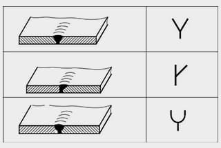
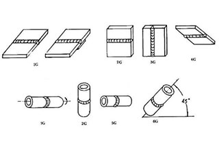
“6” indicates the oblique welding position, “G” represents the groove, as it is the first letter of the word “groove,” and “R” stands for obstacle ring.
The assembly and positioning of the welded pipes are crucial in ensuring the quality of the 6GR welding and the proper shape of the back side of the pipe joint.
If the groove type, assembly gap, and the size of the blunt edge are not suitable, it can easily lead to defects such as collapse, overlap, and incomplete penetration.
The shape of the pipe to be welded is depicted in Figure 1.
Figure 1 Pipe fitting form
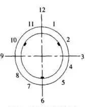
To ensure proper pipe alignment, the pipe butt joint should be performed on a specialized pipe aligner, and the positioning should be secured with rib plates (fixed at 2 points, 10 points, and 6 points).
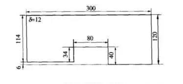
The rib plate is made of 20 steel, and its shape is depicted in Figure 2.
The location of the rib plate positioning is shown in Figure 3.
6GR Operation Features and Difficulties
The 6GR pipe features an obstacle ring, and the difference in thickness between the inner walls of the two pipes is 6mm.
The technical requirement states that the back side of the pipe should be flush with the inner wall of the thick-walled pipe.
However, the back side of the pipe should actually be formed as a full penetration fillet weld.
Backing welding can be challenging.
After extensive exploration and practice, we have found a practical method that meets the requirements.
Backing weld
The main challenge in backing welding is the oblique and oblique welding position of the pipe. Due to uneven heating of the pipe, it becomes difficult for the molten droplet to transfer to the back weld, as gravity causes the molten droplet to flow down. To overcome these challenges, it is important to adjust the arc starting current of the welder to position 5 and the arc blowing force current to position 7 before welding. This makes it easier to start the arc, improves the arc’s stiffness, and helps utilize the arc blowing force to transfer the molten iron to the root of the thick wall pipe, ensuring proper double side forming of single-sided welding.
The welding rod should strike the arc approximately 5mm after 6 o’clock. After ignition, the welding rod should be moved slightly up and down in the groove. Once the root has melted and formed a molten hole, the welding rod should quickly raise and lower the arc. The angle of the welding rod should be inclined towards the side of the thick wall pipe. The small oblique serrations are used to move the electrode back and forth, and the movement should be fast, uniform, and stable.
The welder should pay close attention to the welding rod, using their senses to “look”, “listen”, and “feed”. “Looking” involves observing the temperature of the molten pool and the shape of the molten hole, making sure they remain the same, and ensuring that the arc length melts the root of the thick wall pipe. The size of the molten pool should be 1/2 inside and 1/2 outside the groove. The timing for each arc follow-up should be based on the proximity of the molten pool to solidification. If the follow-up is too fast, the liquid molten pool will increase and the liquid metal will flow down and form weld beading. If the follow-up is too slow, the liquid molten pool will be compressed inward, leading to a depression in the back weld. Generally, the feeding time of liquid metal should be controlled within 1 to 1.5 seconds each time.
“Listening” involves paying attention to the “plop” sound from the edge of the pipe groove caused by arc breakdown. Feeding” involves adjusting the arc length and molten pool size through appropriate arc length, electrode angle, welding speed, and electrode handling method to accurately send molten iron to the root of the groove. If these three elements are properly coordinated, good reverse forming can be achieved.
During arc extinguishing, a molten hole should be created above the molten pool, then the molten iron should be slowly brought back 10 to 15mm, stopping the arc at the groove side to slow the solidification speed of the molten pool and prevent cold shrinkage holes. The joint should form a slope to facilitate the next joint. It is not allowed to back weld and stop the arc at the center of the weld pool or directly stop the arc on the weld pool, as this may generate cold shrinkage cavity on the surface of the back weld pool, making it a difficult defect to repair.
When the arc crater is still red hot, the arc should be started on the slope 10 to 15mm below the weld pool and welded to the arc crater. As the temperature of the arc crater gradually rises, the electrode should be pushed along the prepared hole to the root of the groove. After hearing the “plop” sound, a slight pause should be taken, the welding rod should be moved laterally, and then normal welding should resume. The key to this stage is to transport the welding rod in place, replace it quickly, accurately observe the melting hole, and maintain stable movement. The joint should be hot connected as much as possible to ensure a smooth and beautiful appearance
Filler welding
Upon completing the backing welding, use an angle grinder to smooth out any uneven joints. Set the arc blowing force (thrust) to position 5 and use this force to remove slag on both sides of the weld. This will help prevent slag inclusions.
The electrode should be moved in a zigzag pattern, pausing at both sides of the groove. The molten pool should be kept horizontal at all times.
Remember to stagger the starting and ending points of adjacent layers by 10 to 15mm.
After filling welding is finished, the weld should be 1 to 2mm lower than the base metal to make it easier to weld the covering layer.
Cover welding
Before welding, adjust the arc blowing force (thrust) to position 2. This reduces the arc blowing force, making the arc more flexible, and helps prevent undercut defects in the weld. It also results in a smoother and more visually appealing weld.
A triangular shape should be formed at the overhead welding position using the first half of the welding rod. Welding should then be performed in a horizontal direction using a crescent shaped electrode.
When the welding rod reaches the edge of the groove, pause briefly while keeping the molten pool horizontal.
After striking the arc at the oblique overhead welding position of the second half of the welding rod, pull the triangular area to be welded horizontally towards the lower edge of the groove. The molten pool should overlap the weld made in the first half of the rod. Use a transverse serrated electrode moving method for this.
In the second half of the closing method, reduce the weld pool one by one as the electrode is transported to the closing position. Fill the triangular area before stopping the arc.
The cover layer welding should have a flat arc stopping and arc extinguishing part, and the crater should be filled before extinguishing the arc.
As the founder of MachineMFG, I have dedicated over a decade of my career to the metalworking industry. My extensive experience has allowed me to become an expert in the fields of sheet metal fabrication, machining, mechanical engineering, and machine tools for metals. I am constantly thinking, reading, and writing about these subjects, constantly striving to stay at the forefront of my field. Let my knowledge and expertise be an asset to your business.
Welding symbols may seem like a foreign language, but mastering them is crucial for effective communication in the world of mechanical engineering. In this blog post, a seasoned mechanical engineer…
Ever wondered how skyscrapers stand tall or cars stay welded together? This blog uncovers the magic behind electric welding machines. Learn about top manufacturers like Lincoln Electric and Miller Welds,…
Have you ever wondered how the sleek cars, sturdy bridges, and advanced airplanes of today are built? This article explores six cutting-edge welding technologies that are revolutionizing manufacturing, from laser…
Have you ever wondered why some welded structures fail unexpectedly? This article explores the hidden forces at play—welding stress and deformation. Learn how these stresses impact strength, stability, and accuracy,…
Have you ever wondered how to calculate the consumption of welding rods accurately? In this blog post, we'll explore the methods and formulas used by industry experts to estimate welding…
Have you ever wondered about the art of welding and the different positions involved? In this fascinating blog post, we'll delve into the intricacies of welding positions, from flat to…
Ever wondered what "X-weld" or "tack-weld" means? Our latest article breaks down 292 crucial welding terms, offering clear definitions and practical examples. Whether you're a seasoned welder or just starting,…
Why does argon arc welding sometimes produce pores, and how can we fix it? Welding porosity, often caused by impurities, improper gas flow, or incorrect technique, can weaken welds and…
Imagine a machine that welds with precision, never tires, and enhances safety in industrial settings. This article explores the fascinating world of arc welding robots, detailing their components, operational procedures,…