Basics of Full Penetration First Level Weld Seam Welding
1. General requirements The stress transfer welding encompasses full penetration first-level welds that can handle all types of stress similarly to the base metal, fillet welds that primarily resist shear forces, and partial penetration second-level welds. When fully managed, full penetration first-level welds, excluding low stress and high cycle fatigue such as crown block beams, […]
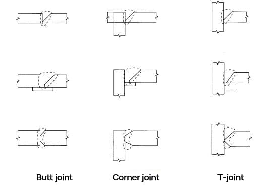
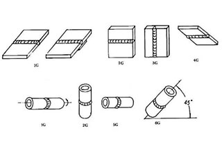
Figure 1 illustrates that joints welded with full penetration first-class welds can be classified into butt joints, corner joints, and T-joints based on the component shape.
The stress transfer welding encompasses full penetration first-level welds that can handle all types of stress similarly to the base metal, fillet welds that primarily resist shear forces, and partial penetration second-level welds.
When fully managed, full penetration first-level welds, excluding low stress and high cycle fatigue such as crown block beams, are considered to exhibit the same performance as the base metal under all loads, including earthquakes and other repeated loads in commonly used building steel.
The full penetration first-level weld must be fully welded on the entire section, and the strength of the welding position must be equal to or greater than that of the base metal.
The throat thickness of the full penetration first-level weld must not be less than the thickness of the base metal (the thickness of the thinner base metal should be used if the base metal thicknesses are different, and the thickness of the base metal to be butt welded should be used if corner joints and T-joints are utilized).
If the throat thickness is smaller than the base metal thickness, it will not only fail to meet the design tolerance but also become a source of stress concentration.
Similarly, if the welding crown is too high, it will also cause stress concentration, and it is necessary to keep the welding crown to a reasonable size.
Full penetration first level weld joint
For instance, when T-joints and corner joints are subjected to forces that pull the steel plates in the direction of the plate thickness, it’s important to note that although there may be no welding defects, the steel plates can still crack due to low strength.
It’s widely known that the ratio of strength or elongation in the thickness direction to the rolling direction of rolled steel plates is generally reduced.
In particular, when non-metallic inclusions (such as MnS) are deflected during the rolling of steel, they can crack or peel under very low stress.
As a result, steel plates used for parts subjected to tensile forces in the direction of plate thickness, such as the top column flange in the case of column penetration or the beam flange of outer columns and corner columns in the case of beam penetration, should be carefully reviewed and considered.
In continuous casting, differences in solidification temperature or reductions in surface temperature can lead to a deflection of MnS components in the center of the plate thickness and a tendency for Al2O3 segregation on the surface layer. However, these issues have improved in recent years.
Recently, with the increasing scale of construction, there have been several reports of lamellar weld cracking due to multi-layer welding of thick steel plates.
T-type full penetration first-class weld joints are typically used in the column beam joints of steel structures that experience maximum stress and repeated plastic strain. This part is the most susceptible to layer welding cracking.
Therefore, it is necessary to select a high-quality steel plate, review the welding design and construction methods, and pay close attention to preheating management to prevent low-temperature cracking of other heat-affected parts.
2. Groove shape
The shape of the groove in the welded joint is a crucial factor for the stability of both sides of the joint.
Incorrect root gap or groove angle can negatively impact the quality of the welded joint.
It is therefore important to determine the appropriate groove shape based on the type of welding method and joint being used.
For conventional welding methods, the standard groove shape for the joint type and root surface size is acceptable as long as the root surface size is less than 2mm when using a backing plate.
For specialized welding methods or joint types, the data should be evaluated to ensure that the groove shape meets quality and construction standards, based on their specific conditions.
3. Welding crown
To prevent stress concentration, the weld crown in the first level full penetration weld should not be overly pronounced. The weld crown should have a smooth and uninterrupted surface from the base metal, with a height ranging from 0 to 3mm.
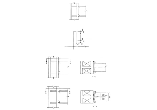
4. Crown height of T-joint
The welding crown in T-joints should reduce stress concentration around the welding area, which is crucial in avoiding cracking or spalling in the butt plate. The desired welding crown is depicted in Figure 2, and it is important for the weld bead to be smooth. The height of the welding crown (h) should be 1/4 of the thickness of the butt joint, or 10mm if the thickness exceeds 40mm.
Fig. 2 Crown height of T-joint
5. Run-on plate
Poor penetration or air holes are commonly seen at the beginning of welding, while crater cracks and other defects often appear at the end. To avoid such defects in effective welding, a steel run-on plate with a suitable shape should be placed at the start and end of the welding, as shown in Fig. 3.
There is no need to remove the run-on plate after welding and its residue is not problematic, as indicated in Fig. 4. However, if the slab thickness exceeds 50mm and the column and beam have the same width, it should be cut.
For instance, when the crown block beam experiences low stress and high-cycle fatigue, it should be cut and refined using a grinder.
It is not recommended to directly assemble and weld the run-on plate at the column beam joint. This is because the short weld bead created during the assembly welding of the run-on tab reduces the fracture toughness of the heat-affected area, potentially making it the starting point of brittle failure of the entire flange plate.
Fig. 5 provides an example of arc strike plate assembly and welding at the column beam joint.
The run-on plate device is assembled and welded onto the backing plate. If it is unavoidable to do so in the groove, the construction must fully ensure the quality of the welding part after the positive welding. However, in practice, the construction conditions are more stringent than forward welding, resulting in inadequate assembly welding quality.
It is necessary to remove or remelt the assembly weld bead during forward welding, especially for critical joints such as full penetration welding, using one of the following methods:
Remove the assembly weld bead with gas arc before welding.
Use a backhoe to remove residual assembly welding at the first welding end.
Re-melt the assembled weld bead without residual defects.
Assembly welding is performed using either electric or gas shielded welding. When welding thicker plate steel with a shorter weld bead length, the welding part may become hardened by rapid heating and cooling and cracking may occur due to the amount of diffusible hydrogen and degree of restraint. This tendency is more pronounced with thicker plates or higher alloy composition.
Therefore, low hydrogen electrodes should be used for assembly welding with covered electric welding, based on the plate thickness and steel type. However, it may be difficult to change the electrode depending on the thickness and grade of the steel, so it is recommended to use low hydrogen electrodes consistently when using covered electric welding.
Gas shielded welding is also effective in preventing cracking due to its low diffusible hydrogen gas, and should be used in assembly welding. Preheating is also effective in preventing cracking and should be conducted under the same conditions as normal welding during assembly and welding.
Other methods to replace the run-on plate method include using sintered fixed run-on plates made of flux, ceramics, or stamped steel plates, or using the backing plate method, back welding method, end removal method, and other methods to eliminate run-on plates.
This method is applicable for flat welding and steels Q235 and Q345. However, if the weldability test confirms that the quality of the welding part is equal to or higher than that of the steel run-on plate construction method, it can be used outside of this scope.
The welding technician must be qualified in the equivalent welding method and recognized by the project supervisor through the additional examination of welding technology for the equivalent run-on plate method.
The most common considerations for fixed type run-on tabs in construction methods are outlined below:
To maintain the joint performance, the material of the fixed type run-on tab should not interfere with the welding metal at the welding position.
The backing plate is in place to prevent the weld metal from dripping at the end of the welding process and should extend about 10mm from the base metal end.
The fixed type run-on tab is securely attached to the base metal using methods such as steel wire or magnet fixtures.
As for the welding method, as depicted in Fig. 6, the arc is started at the point where the base metal end enters 15-20mm and then turns back to ensure full penetration at the end during the initial layer of welding.
6. Joints with different plate thicknesses
When the materials used in butt joint welding have different thicknesses, the welding should be performed from the thinner material to the thicker material to ensure smooth stress distribution.
As shown in Fig. 7 (a), when the difference in thickness exceeds 10mm due to varying plate thickness or when the crown block beam is subjected to low pressure and high cyclic fatigue, the thicker sheet should be angled at less than 1/2.5 and the groove should be made thinner. The sheets should be at the same height.
However, as depicted in Fig. 7 (b), when welding the wing plate joint of an SRC beam formed through an arch head on both sides (backhoe), if the difference in plate thickness exceeds 10mm, reinforcement fillet welding should be used.
It should also be noted that single-side welding of the backing plate should be approved by the project supervisor.
7. Air gouging
When welding from both sides, air gouging should be performed as a general principle before welding the first layer on the back.
The first layer of surface welding is often prone to defects such as cracking, poor penetration, and slag inclusion due to its fast cooling speed. To address these issues, air gouging is necessary to remove any defects in the first layer of the surface.
However, if a construction test or non-destructive inspection is used during submerged arc welding to verify that the first layer on the back has good penetration, air gouging can be omitted.
8. Backing plate
To ensure proper root penetration when using a backing plate, sufficient root clearance must be provided to ensure a close connection. If the backing plate is not tightened completely and the root gap is too small, it can result in welding defects such as poor penetration or slag inclusion at the root.
The backing plate should generally be made from Q345B material. For other materials, it is important to examine their chemical composition (P, S, Cu, C, etc.) to confirm that they are suitable for welding.
In general, the backing plate for the column beam joint should be installed inside the wing plate. However, the lower flange plate may be installed on the outside if necessary for on-site welding. The position of the backing plate is shown in Figure 8.
The assembly welding of the backing plate is subject to tensile stress and minor bending stress, with the fillet welding experiencing the maximum stress. This type of welding is relatively simple, but it is also prone to breaking. In many cases, the assembly welding is performed without preheating the fillet welding.
While the original weld bead length may be sufficient, the fracture toughness of the welding metal or heat-affected zone (HAZ) is low, which can lead to brittle failure of the entire joint if the fillet welding fractures.
As a result, the assembly and welding of the backing plate at the column beam joint should not be carried out within 10mm of either end of the beam flange or within 10mm of the R toe or fillet weld toe of the web fillet [Figure 9 (1)]. The assembly and welding should instead be performed at the position of the run on plate [Figure 9 (2)] or 1/4 of the width of the beam wing plate [Figure 9 (3)]. If the run on plate is installed on the outside of the backing plate or beam flange, it should not be assembled and welded on the outside of the beam flange and column flange [Figure 9 (2)].
As the founder of MachineMFG, I have dedicated over a decade of my career to the metalworking industry. My extensive experience has allowed me to become an expert in the fields of sheet metal fabrication, machining, mechanical engineering, and machine tools for metals. I am constantly thinking, reading, and writing about these subjects, constantly striving to stay at the forefront of my field. Let my knowledge and expertise be an asset to your business.
Is full penetration welding always superior to deep fusion welding? This question puzzles many in the metalworking industry. This article breaks down the strengths and weaknesses of both techniques, detailing…
Imagine achieving a perfect weld with just one pass! Single-side welding and double-side forming make this possible, ensuring full penetration and impeccable quality without reworking the backside. This article dives…
Have you ever wondered about the art of welding and the different positions involved? In this fascinating blog post, we'll delve into the intricacies of welding positions, from flat to…
Ever wondered what "X-weld" or "tack-weld" means? Our latest article breaks down 292 crucial welding terms, offering clear definitions and practical examples. Whether you're a seasoned welder or just starting,…
What if you could ensure your welds are perfect every time? In this article, we'll explore the welding process evaluation, a crucial method for testing and refining welding techniques. You'll…
Have you ever wondered how welding transforms separate metal pieces into a unified whole? This article explores the fascinating world of weld joints, examining their types, mechanical characteristics, and the…
Have you ever considered the challenges of welding galvanized steel pipes? The zinc coating that protects these pipes also introduces issues like cracks, porosity, and slag inclusion during welding. This…
What makes welding magnesium alloys so challenging and exciting? In this article, you'll explore innovative techniques like laser welding with silicon carbide, pulsed current plasma arc welding, and activated welding.…
Ever wondered how welders achieve perfect joints in challenging positions? 6GR welding is a specialized technique for welding pipelines with an obstacle ring at a 45° angle, crucial for ensuring…