Pipe bending is essential in many industries, but defects can compromise both safety and quality. Imagine discovering ways to prevent these issues before they start. This guide dives into common pipe bending defects like flattening, thinning, cracking, and wrinkling, explaining their causes and how to avoid them. By the end, you’ll know the practical steps to ensure your pipes meet the highest standards. Ready to enhance your pipe bending skills and produce flawless bends? Read on to find out how.
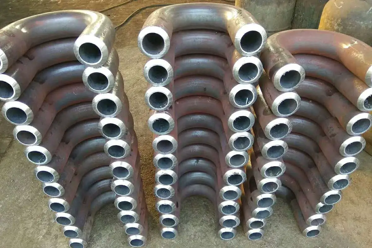
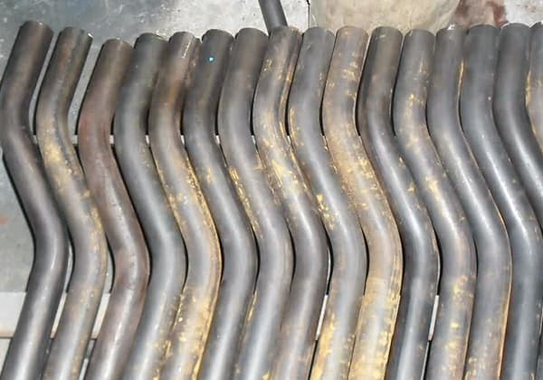
Bent pipe fittings are extensively used in a variety of products in the mechanical industry and oil field capacity construction, such as chemical container manufacturing, water supply pipeline installation, and boiler pressure vessel fabrication.
However, both cold bending and hot bending may result in various defects of different degrees due to improper process conditions or operations. These defects directly affect the safety and appearance quality of the final product.

For instance, the water-cooled wall pipes and convection pipes of boilers are eroded by water and steam on one side and flushed and corroded by flue gas on the other side. Also, the range of pressure and temperature changes is quite large.
If there are defects in the pipe fittings, it will affect the safe operation of the entire unit. Pressure vessels, due to their pressurized operation, will have reduced pressure resistance if the pipe fittings are defective, thus affecting their safety.
Therefore, it is particularly important to identify the causes of various defect types and take corresponding preventive measures.
Common defects of bent pipes mainly include the following forms: severe flattening at the arc (elliptical), severe thinning of the outer wall of the arc, breakage on the outer side of the arc, and wrinkling on the inner side of the arc, as shown in Figure 1.
These defects do not necessarily occur simultaneously, and the ways and locations they occur can vary with the radius of the bent pipe.
However, corresponding measures should be taken to prevent them before bending.
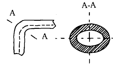


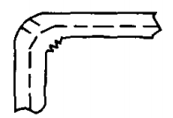
Figure 1: Common Defect Types in Tube Bending
From a process perspective, it is known that when a tube with an outer diameter D and wall thickness S is subjected to an external torque M, causing it to bend, the outer side of the neutral layer of the tube wall thins due to tensile stress, while the inner side thickens due to compressive stress (see Figure 2a).
Concurrently, the combined forces deform the cross-section of the bend into an approximate elliptical shape (see Figure 2b). Under the influence of compressive stress, the inner wall of the tube may become unstable and wrinkle (see Figure 2c).
Generally, for bending radii ≥3D, satisfactory bent tubes can be achieved. However, when the bending radius <2D, especially when R/D or S/D decreases (i.e., the bending radius R is small, the tube diameter is larger, and the wall is thinner), the mentioned defects are likely to occur.
Moreover, during the operation process, improper mold installation and other factors can also lead to various types of defects in the bent tubes.


Figure 2: Stress and Deformation in Pure Bending of a Tube
Below we conduct a detailed analysis of the causes of defects that occur during small-radius tube bending:
During tube bending, the combined forces F1 and F2 cause the cross-sectional area at the arc to trend towards an elliptical shape.
For a tube of the same specification, the smaller the bending radius, the greater these forces, and the more apparent the flattening. If the tube is bent without a mandrel, the flattening is more severe.
If a mandrel is used, but its diameter is too small or it is severely worn, causing a large gap between the mandrel and the inner wall of the tube, the outer side of the arc can also easily flatten.
Even if the gap between the mandrel and the tube wall is reasonable, if the mandrel is installed too early, the tube wall will not be well supported, and the outer side of the arc will also flatten.
Additionally, if attention is not paid during mold installation and the bending mold and compression mold (wheel) faces are misaligned, the tube at the arc will also flatten.
When the bending radius is small, if the tube bender does not have an outer side booster device and a tail-end pushing device, the resistance of the compression mold will increase the tensile stress on the outer side of the arc, causing the neutral layer to shift inward.
This results in the outer side of the bent pipe thinning, and the more the compression force, the more the resistance and the more the thinning. This is especially true when the relative bending radius R/D and relative wall thickness S/D are smaller, which makes the thinning more apparent.
Apart from factors such as the tube material and bending radius, factors like the oversize of the mandrel installation and poor lubrication will also increase the thinning of the outer side of the tube wall.
Cracks or breaks on the outer side of the arc during tube bending can be caused by various factors.
These include improper heat treatment of the tube material, excessive grain size, excessive pressure from the compression mold (wheel) causing high bending resistance, a too-small gap between the mandrel and the inner wall of the tube causing high friction, poor lubrication, excessive bending force causing machine vibration, and others.
There are three common situations where wrinkling occurs on the inner side of the arc: wrinkling at the front tangent point, at the back tangent point, or over the entire inner side of the arc.
Wrinkling at the front tangent point is generally due to undersized pre-installation of the mandrel, where the tube wall at the front tangent point is not well supported during bending.
Wrinkling at the back tangent point is typically because no anti-wrinkling mold was installed, or the anti-wrinkling mold and the bending mold were not properly aligned at the tangent point.
Full wrinkling usually occurs if the mandrel diameter is too small, creating a large gap between the mandrel and the tube wall, leading to easy wrinkling.
It can also be due to insufficient pressure from the compression wheel, preventing the tube from properly aligning with the bending mold and anti-wrinkling mold during bending, leading to instability and wrinkling under compressive stress.
To prevent or mitigate tube bending defects and produce tubes that meet requirements, appropriate countermeasures should be adopted during the bending process.
Within the allowable range of product design structure, a larger bending radius should be used as much as possible. For the common defects mentioned above, targeted measures should be taken.
3.1 For tubes with severe flattening on the outer side of the arc, when performing mandrel-less bending, the compression mold (wheel) can be designed with an anti-deformation groove structure to reduce the degree of flattening during bending.
For mandrel bending, the wear of the mandrel should be checked periodically to ensure that the unilateral gap between the mandrel and the inner wall of the tube is no more than 0.5mm. Also, the pre-installation size of the mandrel should be appropriate.
3.2 Thinning on the outer side of the arc during small radius tube bending is a characteristic of the bending process and is inevitable.
However, measures should be taken to overcome excessive thinning. A common effective method is to use a bender with a side booster and a back end pusher.
During operation, the booster or pusher propels the tube forwards, offsetting some resistance during bending, improving the stress distribution on the tube’s cross-section, and displacing the neutral layer outward, thereby reducing the thinning on the outer side of the arc.
The speed of the booster and pusher is determined according to the actual bending conditions, so that it matches the bending speed.
3.3 For situations where the tube cracks on the outer bend of the arc, it is essential to first ensure that the tube material is in a good heat treatment state.
After excluding factors related to the tube material, check whether the clamping mold’s pressure is too high and adjust it to be just right.
Check if the core rod diameter is too large, and if so, grind it down, ensuring that the core rod and the tube’s inner wall have good lubrication to reduce bending resistance and friction. At the same time, take appropriate measures to avoid machine tool vibration, etc.
3.4 For wrinkling on the inner side of the arc, measures should be taken according to the location of the wrinkles.
If the wrinkles form at the front cutting point, adjust the position of the core rod forward, making the core rod’s lead appropriate to achieve reasonable support for the tube during bending.
If the wrinkles form at the back cutting point, install an anti-wrinkle block, ensure its correct installation position, and adjust the pressure of the clamping mold (wheel) to be appropriate.
If there are wrinkles all over the inner side of the arc, apart from adjusting the clamping mold (wheel) to make the pressure appropriate, also check the core rod diameter – if it is too small or severely worn, replace the core rod.
In the tube bending process, different types and degrees of defects may occur due to improper techniques and operation.
Therefore, the causes of various types of defects should be specifically analyzed, and corresponding measures should be taken according to different situations.
This can reduce or even eliminate the occurrence of defects, thereby producing better bent tubes.

