Bending tubes precisely requires understanding specific guidelines and parameters. How do you ensure a smooth, accurate bend every time? This article explores the crucial aspects of tube bending, including machine parameters, die installation, and common defects. Learn how to set up and adjust your equipment, calculate bending angles, and prevent issues like cracking and wrinkling. Discover practical tips and techniques that can help you achieve optimal results in tube bending operations.
1.1 This procedure is applicable for the CNC pipe bending machine used for cold bending of metal pipes.
1.2 This procedure is applicable for DW63 and DW114 model single-head hydraulic pipe bending machines in the agricultural equipment structural parts workshop.
2 . Normative reference documents
The following documents are essential for the application of this document. For the reference documents dated, only the version dated applies to this document. For undated reference documents, the latest version applies to this document.
GB/T 28763-2012 CNC Pipe Bending Machine
3 . Terms and Definitions
CNC Pipe Bending Machine: A pipe bending machine that should have at least three-axis movement, including spindle rotation, chuck linear motion, and chuck rotation, and is controlled by a CNC system.
4 . Pipe Bending Machine Parameters
4.1 The main parameter of the pipe bending machine is the maximum outer diameter of the pipe.
4.2 The main parameters and basic parameters of the pipe bending machine should conform to the rules prescribed in the table below.
Parameter Name
Maximum Tube Outside Diameter/mm
Maximum Tube Wall Thickness/mm
Parameter Value
10
1.2
16
1.2
25
3
38
4
42
4
60
5
63
5
76
5
89
6
114
8
159
12
168
12
219
16
273
20
When the outer diameter is greater than or equal to 114mm, it is 0.4 to 1 times the maximum radius of the bent pipe.
4.4 Structural parts workshop pipe bending machine parameters:
5. Existing Pipe Bending Dies in the Structural Component Workshop
Material Type
Material Specification mm
Wall Thickness mm
Bending Radius (Default as Median) mm
Corresponding Equipment
Square Tube
φ16
2
58
DWFB63
φ25
2
50
DWFB63
φ25
2
150
DWFB63
φ33
3
101.5
DWFB63
Φ35
4
60
DWFB63
Φ42
3
100
DWFB63
Φ48
3.5
130
DWFB63
Φ50
6
100
DWFB114
Φ60
5
150
DWFB63
Φ60
5
200
DWFB63
Φ60.5
2
150
DWFB114
Round Tube
Square tube 30×30
2
外径220
DWFB114
Square tube 40×80-8
2.5
100
DWFB114
Square tube 40×80-8
3
180
DWFB114
Square tube 40×80-8
2
Outer Diameter: 220
DWFB114
Square tube 50×50
2.5
Inner Diameter: 170
DWFB114
Square tube 50×70-7
2.5
120
DWFB114
Square tube 50×70-7
3
120
DWFB114
Square tube 60×80-6
4.5
150
DWFB114
Square tube 60×80-8
4.5
150
DWFB114
6. Installation and Adjustment of the Mold
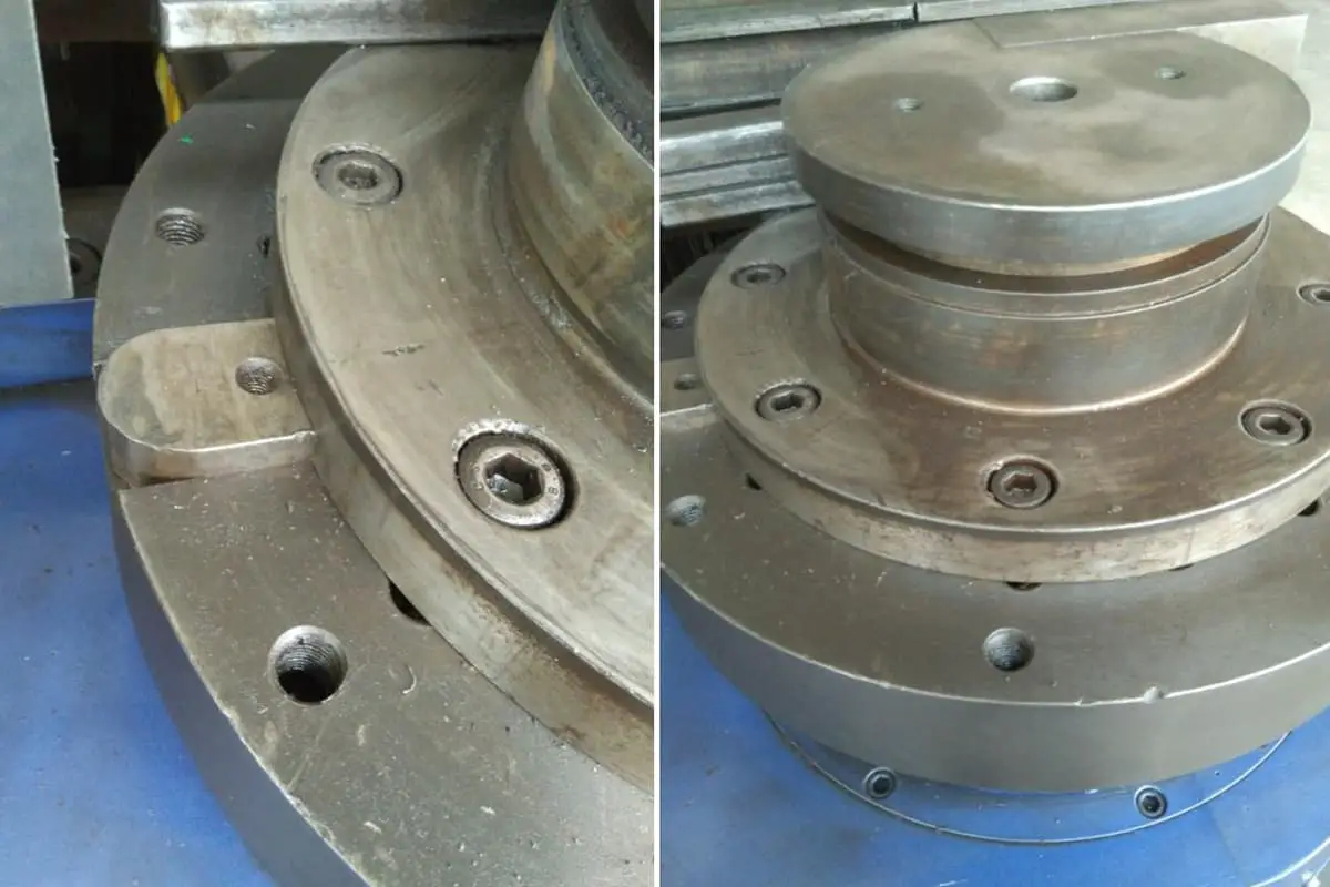
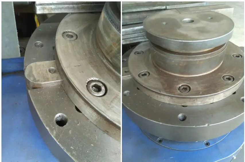
6.1 Installation of the Main Mold
6.1.1 Place the bending wheel mold with the key slot facing downwards onto the fixed seat matching key. After placing it flat, adjust the wheel mold left and right so that the bolt hole of the wheel mold coincides with the bolt hole of the fixed seat.
6.1.2 Tighten the fixed nut, there should be no looseness.
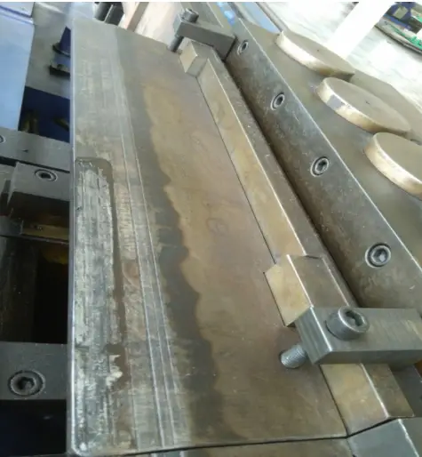
6.2 Installation and Adjustment of Pressing Molds
6.2.1 Secure the press mold to the slider with bolts, rotate the adjustment bolt, move the clamp mold up and down, align the center of the press mold with the center of the bending mold groove to ensure a tight fit between the two during the press mold feed, without any interference.
6.2.2 Loosen the fixing nut of the press mold slider, then use a wrench to loosen the slider adjustment bolt.
6.2.3 Place a test mold material of about 300mm long into the wheel mold bending groove. Control the pressure mold to clamp the pipe forward and there should be no loosening. Tighten the pressure mold slider adjustment bolt with a wrench. Control the pressure mold to retreat, then tighten the pressure mold slider adjustment bolt again by half a turn with a wrench. Finally, tighten the pressure mold slider fixing nut.
6.3.1 Connect and fix the clamping mold and slider with bolts. Rotate the adjustment bolt, move the clamping mold up and down to make it the same height as the main clamping mold.
6.3.2 Loosen the fixing nut of the clamp die slider, and use a wrench to loosen the slider adjustment bolt.
6.3.3 Place a test mold segment approximately 300mm in length into the wheel mold pipe groove and tighten the mold clamp slider adjustment bolt with a wrench to clamp the pipe. There should be no loosening. Remove the test mold pipe, use the wrench to further tighten the mold clamp slider adjustment bolt by 1/3 of a turn, and tighten the mold clamp slider fixation nut.
6.4 Core Rod Installation and Adjustment
6.4.1 Connect the threaded hole of the core rod with the core rod draw-bar bolt. After tightening, adjust the rear seat of the core rod draw-bar so that the tangent position of the arc surface on the core rod in the horizontal direction does not cross the center line of the bending mold.
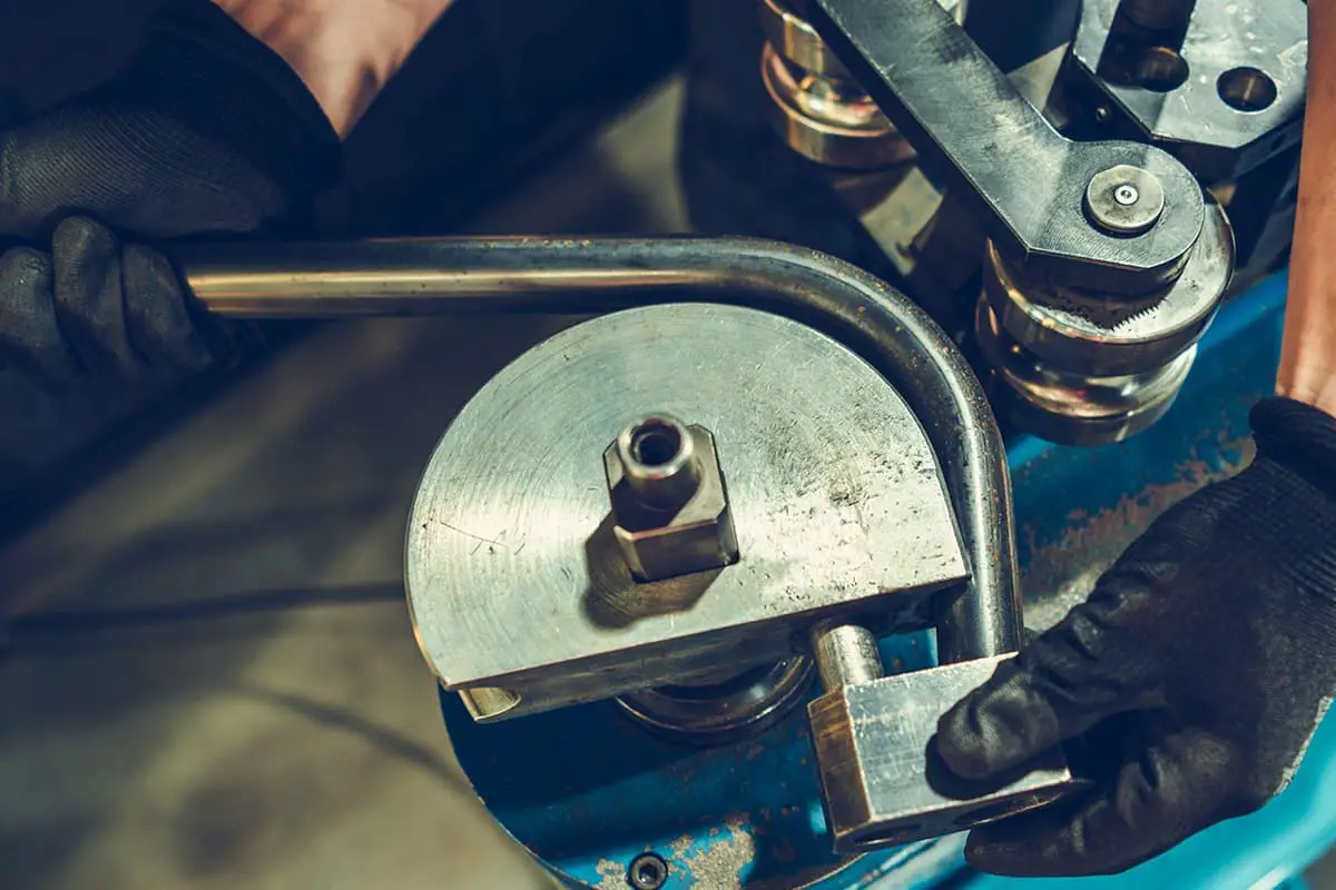
7. Calculation and Cutting of Bent Pipes
7.1 Calculation for 90° Bent Pipes
For cold-drawn bent pipes, take R=(4~6)D. As shown in Figure 1-3, after the pipe is bent, the lengths of the outer arc and the inner arc of the bent segment are not the actual length of the original straight pipe, but only the length of the centerline of the bent pipe remains unchanged before and after bending.
Its unfolded length is equal to the length of the original straight pipe section. Now assume the starting and ending points of the bent section are a and b respectively. When the bending angle is 90°, the length of the bent section of the pipe is exactly 1/4 of the circumference of the circle drawn with r as the radius. Its arc length is represented by the bending radius, which is:
Arc length ab=2πR/4=1.57R
From formula (1-3), it can be known that the unfolded length of the 90° bend is 1.57 times the bending radius.
An arbitrary bending pipe refers to a pipe with an arbitrary bending angle and radius. The unfolded length of the bending part of this pipe can be calculated using the following formula:
L=παR/180=0.01745αR
In the formula, L is the unfolded length of the bent part (mm); α— is the bending angle (°); π— is Pi; R is the bending radius (mm).
In addition, the calculation of the unfolded length of any bending pipe segment can also be carried out according to Figure 1-6 and Table 1-1.
Figure 1-6 Arbitrary Pipe Bending
The following example illustrates how to use Table 1-1.
When using the values of C and L from the table, they should be multiplied by the bending radius R. For example, given that the bending angle of the elbow in Figure 1-7 is 25°, the bending radius R=500mm, and the distance from the installed pipe section to the turning point M is 911mm, if you take a straight pipe to make the elbow, how should you mark the line?
Solution:
The length of the straight pipe section at the end of the pipe to be processed, b = 911-CR
From Table 1-1, when the angle is 25°, C=0.2216, L=0.4363; therefore, CR is: 0.2216R=0.2216×500=111mm. Thus, b=911-111=800 mm
The actual unfolded length of the bending part L=0.4363R=0.4363×500=218 mm
Based on the calculated lengths of the straight pipe section b and the unfolded length L of the bending part, you can then mark the line. As shown in Figure 1-7b.
From the examples above, as long as the bending angle and radius are defined, Table 1-1 can be used for convenient calculations of pipe bending of any angle and radius.
8. Preparations Before Starting the Machine
8.1 The pipe bending machine must be operated by specially trained personnel. Unauthorized operation by others is prohibited.
8.2 Operators should wear protective equipment before operation and carefully inspect the machine and working environment. Check the surroundings of the workplace and clear all objects that may hinder work and traffic.
8.3 Before operation, first check whether there is a lack of oil at each lubrication point, whether the moving mechanism is loose, and whether the safety protection device is reliable. After confirmation, operation can be performed; hard objects and pipe fittings must not be used to tap the main control screen.
8.4 After the machine is started, it should be run empty 1-2 times before normal operation. If the machine has been idle for several days, it should be started for ten minutes before normal operation.
8.5 Various shaped materials should use corresponding molds and should not be mixed or misused. Only one shaped material can be bent at a time; it is not allowed to bend two or more superimposed materials to prevent damage to the equipment and molds.
9. Debugging of New Parts and Mass Production
9.1 For the first-time production of workpieces, prepare templates as references. After the molds are installed and debugged as required, and materials are cut according to the theoretical cutting length, mark the bending points, perform bending operations on the material, then compare the bent workpieces with the template.
If there is an error, adjust the cutting length and bending points until there is no error between the bent workpiece and the template, then you can save the cutting size and model program. The next time you make this type of workpiece, you can directly call up the saved data for pipe bending.
9.2 For mass-produced workpieces, prepare templates as references. Call up the saved cutting size and model program, make one piece first, then compare the first piece with the template to determine if there is any error.
If there is an error, fine-tune the cutting size and model program until there is no error between the bent workpiece and the template, then you can save the data for mass production.
10. Common Pipe Bending Defects and Preventive Measures
10.1 Severe flattening on the outer side of the arc
During the process of bend-piping with a core, select the appropriate mandrel (if necessary, a flexible mandrel assembled from multiple sections can be used), install it correctly, and ensure that the tube groove axis of all components is on the same horizontal plane when installing the mold.
10.2 Thinning on the outside of the arc
To avoid excessive thinning, a common effective method is to use a pipe bending machine with a side booster device or a tail push device.
By boosting or pushing, some of the resistance during pipe bending is offset, improving the stress distribution on the cross-section of the pipe, moving the neutral layer outward, thereby achieving the purpose of reducing the thinning of the outer pipe wall.
10.3 Cracking on the outside of the arc
First, ensure that the tube material has a good heat treatment state, then check whether the pressure of the clamping mold is too high, and adjust it to an appropriate pressure.
Finally, ensure that there is good lubrication between the mandrel and the pipe wall to reduce the bending resistance and friction between the inner wall of the pipe and the mandrel.
10.4 Wrinkling on the inside of the arc
Appropriate measures should be taken according to the location of wrinkling. If the front cut point is wrinkled, the mandrel position should be adjusted forward to achieve reasonable support for the tube during bending.
If the rear cut point is wrinkled, a wrinkle prevention block should be installed to ensure correct positioning and adjust the die pressure to an appropriate level.
If the entire inner side of the arc is wrinkled, it indicates that the diameter of the mandrel used is too small, causing too large a gap between the mandrel and the tube wall, or the die pressure is too low, which cannot make the tube fit well with the bending die and wrinkle prevention block during bending.
Therefore, the mandrel should be replaced and the clamping die adjusted to provide appropriate die pressure.
As the founder of MachineMFG, I have dedicated over a decade of my career to the metalworking industry. My extensive experience has allowed me to become an expert in the fields of sheet metal fabrication, machining, mechanical engineering, and machine tools for metals. I am constantly thinking, reading, and writing about these subjects, constantly striving to stay at the forefront of my field. Let my knowledge and expertise be an asset to your business.
Have you ever wondered why some tubes wrinkle or tear during bending? This article explores the root causes of these issues, focusing on factors like bending radius, material properties, and…
Imagine bending sheet metal without leaving a single mark or scratch. In this article, we explore innovative techniques for mark-free sheet metal bending, addressing challenges like friction, material hardness, and…
Ever thought bending sheet metal could be so intricate? Closed bending, a critical technique in sheet metal processing, uses specialized methods to achieve precise, durable bends without needing a professional…
Pipe bending is essential in many industries, but defects can compromise both safety and quality. Imagine discovering ways to prevent these issues before they start. This guide dives into common…
In the vast world of manufacturing, one machine stands tall: the press brake. With its ability to bend and shape metal with precision and power, it has become an indispensable…
Have you ever wondered how a simple sheet of metal transforms into a complex, three-dimensional object? Press brake bending, a crucial process in metal fabrication, holds the key to this…
Have you ever considered what holds up the street lights that guide our way home? In this blog, we’ll explore the fascinating world of light poles, from their materials and…