Bend Allowance Formula: Calculator & Charts
Have you ever wondered how to precisely calculate the bending allowance for your metal fabrication projects? In this blog post, we'll explore the fascinating world of bend allowance formulas and…
Have you ever wondered how to bend waveguides with precision? In this article, we explore the advanced techniques used in waveguide bending, essential for enhancing radar system performance. You’ll learn about various bending methods, the technical requirements for accurate bending, and the innovative solutions in automated waveguide bending machinery. This knowledge will help you understand the critical aspects of waveguide bending and its impact on modern technology. Dive in to discover how to achieve optimal bending efficiency and accuracy in your projects.
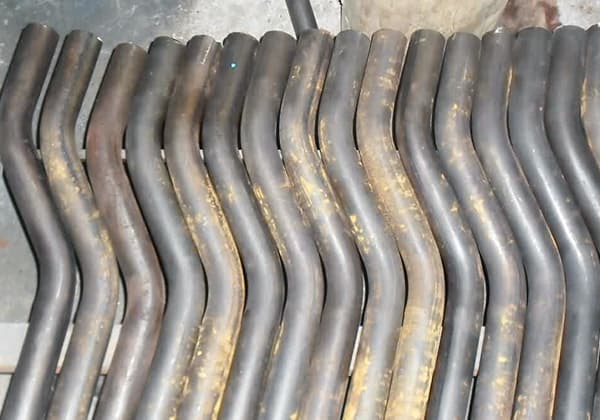
There are many waveguides in the operation of the bending machine. The quality of the bending processing of the waveguides directly affects the performance of the radar system.
In traditional bending processing, the main processing methods used are groove type, rigid core rod type, flexible core rod type, and internal filling type.
However, these methods have low work efficiency, produce few finished products, and have difficulties in processing during use.
Therefore, in the application of waveguide bending technology, it is necessary to reasonably use curved waveguides instead of traditional welding parts to simplify the overall process, reduce production costs, and improve the reliability and effectiveness of equipment processing.

Firstly, bending processing needs to be carried out on both the E and H planes, with the bending angle controlled between 30° to 150°, and the accuracy should be within ±1.6°.
Secondly, the minimum bending radius of the E plane needs to be around 21mm, while that of the H plane needs to be around 41mm.
Finally, the deformation of the inner cavity also needs to strictly control the cross-sectional size within 0.05mm and meet the requirements of electrical performance.
During the bending process of waveguides, not only will there be shape changes in the cross-section but also wall thickness changes.
Therefore, it is necessary to focus on the situation of the inner cavity size during the bending process and understand the specific amount of change.
During the bending process of pipes, it is necessary to understand the compression deformation of the inner part and clarify the thickness and width characteristics.
As for the tensile deformation of the outer surface, it mainly manifests in the increase or decrease of wall thickness, and the width of the side surface will also determine the actual characteristics of the waveguide.
For waveguides, compared with round pipes, rectangular pipes are not self-supported structures, and the flowability of the inner and outer arc lines of the circular metal during bending cannot be guaranteed.
Therefore, it is difficult to form a small radius bending state in actual analysis of rectangular pipes.
Generally, in practical work, it can be assumed that the same deformation resistance force will be generated for metal materials under tension and compression, and the mechanical properties of the metal can be expressed uniformly, thereby forming the same tensile and compression method.
During the actual analysis of the waveguide mold and core rod, it can be regarded as a rigid structure, and the geometric size of the inner cavity of the pipe will not change. Only the stress-strain analysis of the pipe wall needs to be carried out.
At the beginning of the bending process, there is a coincidence phenomenon between the neutral material and the pipe material.
After increasing the deformation, the neutral material will partially move, and the tensile area gradually increases while the compression structure decreases, and the wall thickness on the outer side shows an obvious thinning trend.
During the processing of waveguides with softening characteristics, elastic deformation problems can be ignored. If the value of R/B is very small, then the amount of deformation will be large, and the material will be in a plastic state, and the pipe will also be subjected to certain axial stresses.
Before and after bending, if the position of the neutral layer can be kept unchanged, Y can be used as the main coordinate point, and the formula AY = AS + gb can be used, where G = Y/B represents the stress condition of the fiber layer.
In the process of assuming the section, if it is in the ideal state, the stress distribution of the cross-section can be expressed by Figure 1.
Assuming that the bending angle of the pipe in actual processing is A, and the neutral layer coincides with the pipe, the length of the neutral layer stress can be expressed by the formula L = RA.
In the actual calculation of the material, the length of the outermost layer can be expressed by the formula L = (R + B/2)A, and for the inner material of the bent pipe, the length is l = (R – B/2)A.
The specific technical methods for design work are as follows:
① In the bending design work, it is necessary to fully understand the mechanism and carry out reasonable stress testing to comprehensively understand the deformation characteristics and conditions of the material;
② Repeated experiments are conducted to analyze the bending deformation data information of waveguides under various conditions and obtain accurate parameters of the tensile limit;
③ Develop a perfect bending heat treatment plan, clarify the content of various aspects of work standards, so that the bending force and main thrust force of the waveguide during bending meet the regulations;
④ Reasonably rotate the core rod material and shape during bending;
⑤ Carry out the design of the electronic control machine reasonably according to the relevant accuracy standards of the bending angle;
⑥ During actual design, it is necessary to produce the mechanical properties of the waveguide reasonably.
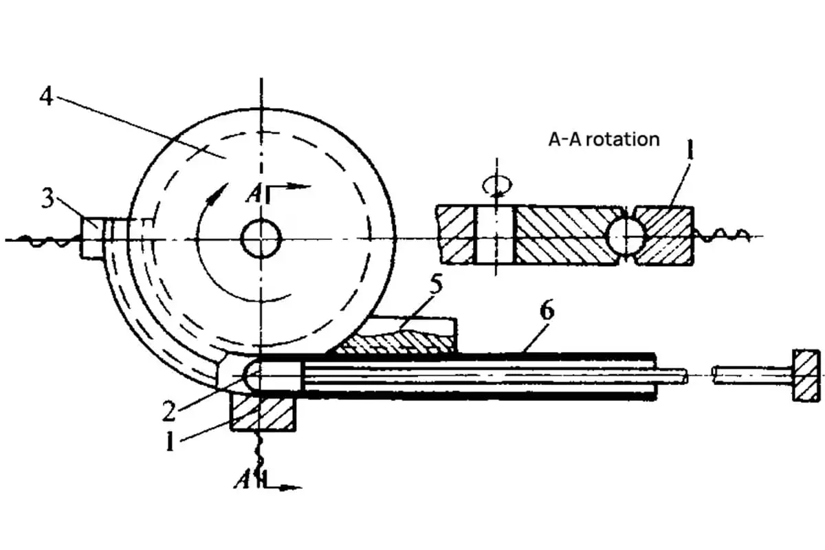
In the actual operation of automatic waveguide bending machinery, the main structural components are the clamping system, loading and unloading system, axial thrust system, main rotation system, control and power system, etc.
During the operation of the loading machine, the clamping system can cooperate to reasonably install and clamp the core rod material.
For the control system, it mainly controls the bending angle comprehensively. The hydraulic cylinder drives the rack to achieve scientific bending processing, comprehensively improve the overall processing level, and meet current development needs.
For the clamping system, it is mainly designed with a crank connecting rod method in actual operation, which can form a high locking force under a small rotating driving force to strengthen the control of the clamping state of the mold during forming.
For the loading and unloading machinery, a double L-type split combination method can be used to rationally design the cavity structure according to relevant bending characteristics.
In the design work, strict discussion and analysis of the rectangular cavity should be carried out, and it should be split along the diagonal direction. If the machine is on the clamping exit turntable, the tube will automatically detach from the mold to complete the unloading task.
During the actual operation of the axial thrust system, the size of the thrust is adjusted based on the curvature radius data information in waveguide bending work, reducing current problems.
During pressure adjustment, the reliability and effectiveness of the thrust can be improved to enhance the effectiveness of loading and unloading core rods.
During the actual operation of the main rotation system, a gear rack system is mainly used to rotate under the drive of the hydraulic cylinder, comprehensively improving the driving force, enhancing the compactness of the structure, improving the stability of the system operation, and enhancing the uniform rotation speed to avoid impact effects.
During the actual operation of the automatic control system, electromechanical integration control technology is mainly used to fully utilize the positive role of programming controllers, achieve the purpose of mechanical coordination and management, and use a rotary encoder to reasonably measure and feedback the bending angle to improve the overall work level.
The use of automatic bending machines for waveguide tubes can reform traditional bending processing methods. In addition to shortening the overall production cycle, it can also reduce production costs and improve the economic benefits of bending processing.
After investigation, it can be found that the processing cycle can be shortened by about 90%, the production cost can be reduced by about 95%, and the yield rate is around 95%.

As the founder of MachineMFG, I have dedicated over a decade of my career to the metalworking industry. My extensive experience has allowed me to become an expert in the fields of sheet metal fabrication, machining, mechanical engineering, and machine tools for metals. I am constantly thinking, reading, and writing about these subjects, constantly striving to stay at the forefront of my field. Let my knowledge and expertise be an asset to your business.