In 2005, our company purchased a world-class forging automatic production line (Figure 1) from Germany. This production line is capable of high-speed forging and has a capacity of 3500t.
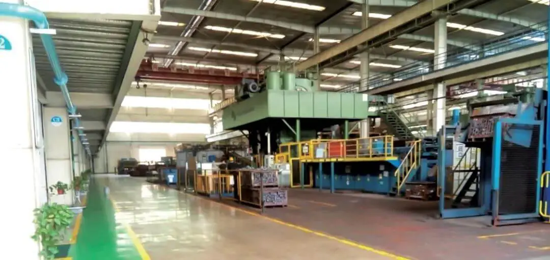
Fig. 1 panorama of 3500t high speed forging automatic production line
The maximum production rate of the design is 25 pieces per minute.
Feeding, heating, forging, and afterheat treatment are all automatically controlled.
The closed forging process is adopted, which involves five steps to achieve forging forming: pre-upsetting, upsetting, pre-forging, final forging, and punching.
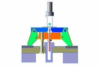
As depicted in Figure 2, the mold cooling system uses automatic spray technology. The cooling medium is a mixture of water and mold release agent in a specific proportion.
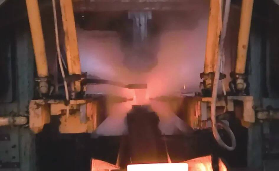
Fig. 2 automatic spray cooling and lubrication
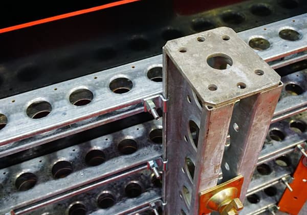
During actual production, it has been observed that certain forging varieties do not reach their normal die life, with the main form of failure being die cracking (refer to Fig. 3).
On average, around 1500 pieces are affected by cracking, resulting in approximately 2500 scrapped molds. In more serious cases, about 300 pieces experience cracking, leading to the disposal of approximately 1200 molds.
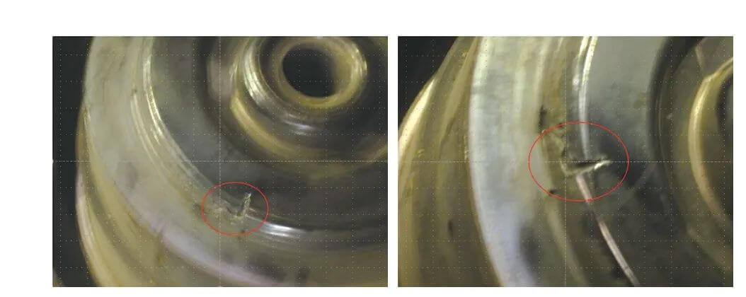
Fig. 3 position and form of mold crack (crack in red circle)
Failure cause finding
The first step involved retrieving the physical and chemical inspection records, as well as the heat treatment physical and chemical inspection records of the die steel. The hardness of the failed die was also verified, and no obvious abnormalities were found.
Secondly, a careful observation of the shape, size, and depth of the crack on the field failure mold was conducted. It was discovered that the crack’s height seemed to have been gradually formed by cutting with high-temperature and high-pressure gas.
The third step was to assemble the upper and lower dies of the final forging and pre-forged hot blanks using CAD (as shown in Fig. 4).
Although a closed space with a height of about 1.9mm was present, with an exhaust hole, it was found that the die crack was apparent during actual production. Therefore, it was necessary to analyze this issue carefully using deform simulation software.
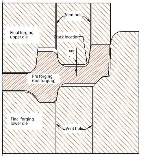
Fig. 4 CAD drawing of final forging upper and lower dies and pre forged hot blanks assembly
Fourth, using Deform simulation and careful observation, it was noted that during the final forging forming simulation, at step 16, the arcs on both sides of the upper die spokes of the final forging first make contact with the hot pre-forged blank. This results in the formation of an independent confined space between the two nearest exhaust holes on the left and right, as shown in Fig. 5.
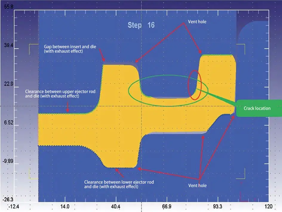
Fig. 5 failure mold deform simulation (independent confined space in the green circle)
After conducting deformation simulation analysis on several abnormal crack dies, it was discovered that an independent confined space is formed during the forging process between the hot blank and the two nearest exhaust holes on the left and right of the upper and lower dies. This phenomenon is depicted in Fig. 6, Fig. 7, and Fig. 8.

Fig. 6 deform simulation of failure mold II (independent confined space in the green circle)

Fig. 7 three deform simulation of failure mold (independent confined space in the green circle)

Fig. 8 deform simulation of four failed molds (independent confined space in the green circle)
The fifth step involves analyzing the information presented above in detail.
The production characteristics of the 3500t high-speed forging automatic production line dictate that when the slider reaches the top dead center, the spray system will rapidly extend into the upper and lower molds of the five steps and apply a significant amount of mold release agent and water mixture onto them for about one second.
Timely application of a large quantity of coolant (i.e., the mixture of mold release agent and water) serves two important purposes. Firstly, it ensures prompt and stable demolding and ejection of hot forgings, and secondly, it helps maintain the working temperature of the die within a specific low-temperature range. This is crucial in preventing the die from being damaged due to severe wear or deformation caused by a sudden temperature rise in a short period of time.
In summary, the timely application of a significant amount of coolant is a crucial measure in ensuring the smooth operation of high-speed automatic forging and is absolutely essential.
During forging, the hot blank (which has a temperature of about 1150300 ℃) at a high speed. This instantaneous contact can cause the coolant to convert into high-temperature and high-pressure gas. However, particularly in an independent confined space, the high-temperature and high-pressure gas cannot be smoothly discharged through the exhaust hole, and it eventually acts on the hot mold, leading to cutting damage.
Improvement measures
Based on the analysis results above, the improvement measures have been formulated.
Initially, the pre-forging die for the previously failed Die I underwent experimental modifications. The spoke surface of the final forging upper die now first contacts the hot pre-forging blank spoke when placed in the final forging cavity for forging. There is no independent confined space between the two nearest exhaust holes on the left and right.
During forging, a large amount of high-temperature and high-pressure gas is generated, which can now be smoothly and timely discharged from the exhaust hole, the gap between the upper and lower ejector rods and the mold, and the gap between the split molds, as shown in Figure 9.
The experimental improvement scheme for the failed Die I has proven to be very successful during practical verification. The mold’s lifespan has now reached 15,000 pieces, and there have been no further mold crack failures.

Fig. 9 deform simulation of failure mold after improvement (there is no independent confined space in the green circle)
Based on successful experimentation, we have sequentially improved other problematic molds. This ensures that when a new hot forging blank reaches the problem step, there will be no isolated confined space between the blank and the two nearest exhaust holes on the left and right sides of the mold. You can find the improvement method detailed in Figures 10, 11, and 12.

Fig. 10 deform simulation after improvement of failed mold II (there is no independent confined space in the green circle)

Fig. 11 deform simulation after improvement of failure mold III (there is no independent confined space in the green circle)

Fig. 12 deform simulation after improvement of failed mold IV (there is no independent confined space in the green circle)
Improvement effect
The molds, namely I, II, III, and IV, were individually improved and the results were highly effective. The average lifespan of the molds has increased to 15,000 pieces with no instances of crack failure.
In addition to ensuring the appearance quality of forgings, significant cost savings can be seen (Table 1) through the reduction of die costs. Furthermore, by avoiding the need for subsequent repair of forgings, unnecessary waste of manpower and material resources is also prevented.
Table 1 cost saving table of improved mold
|
NO. |
Forging demand (10000 pieces / month) |
Mold demand before improvement (piece / month) |
Mold demand after improvement (piece / month) |
Die saved after improvement (piece / month) |
Cost saved after improvement (10000 yuan / month) |
Monthly savings (10000 yuan / month) |
Annual savings (10000 yuan) |
|
Mold I |
3 |
12~20 |
3~4 |
10 |
4.5 |
18 |
216 |
|
Mold II |
|||||||
|
Mold III |
|||||||
|
Mold IV |
Improvement summary
(1)To maintain stable operation of the 3500t high-speed forging automatic production line, a large amount of mist coolant must be sprayed. However, when the spray device malfunctions, such as the air valve failure (resulting in no air for upper and lower mold spray) or water valve failure (upper mold spray valve not spraying, lower mold spray valve spraying for a long time, or both upper and lower mold spraying for a long time), issues can arise.
Moreover, the failure of the release agent valve (upper mold spray release agent valve not spraying, lower mold spray release agent valve spraying for a long time, or both upper and lower mold spraying for a long time) can result in water or a mixture of water and release agent remaining in the low concave of the hot blank. This can lead to the upper mold not being lubricated and cooled on time, which causes a quick temperature rise. The mold is then more prone to being cut and damaged by high-temperature and high-pressure gas.
(2) When high temperature and high pressure gas act on a hot die, it can cause cutting damage. This raises the question why the hot forging is not cut, but only the die.
It was later discovered that hot forging, which has a temperature of about 1150 ~ 1200 ℃, has extremely high plasticity, while the die, with a working temperature of about 200 ~ 300 ℃, does not have the same plasticity.
Both hot forgings and hot dies are subjected to high temperature and high pressure gas, but the cutting trace on hot forgings will repair itself due to their high plasticity. On the other hand, the die must remain at a relatively low temperature to maintain its hardness, and cannot have any plasticity due to a sharp rise in temperature. As a result, even a small crack caused by the high temperature and high pressure gas cutting cannot repair itself, and as the forging and forming work continues, the crack will slowly extend and eventually result in the scrapping of the mold.
(3) Practice has proven that this improvement is successful and the effect is very noticeable, which can be considered as a cure for the problem.
After a long period of observation and verification, the 3500t high-speed forging automatic production line no longer experiences die crack failure.
The relevant designers of the forging process room of the hot forming group of the material physical and chemical center of the group company have also recognized this improvement, and updated drawings have been issued.
Conclusion
The successful resolution of the die crack failure problem in the 3500-ton high-speed forging automatic production line provides valuable insights for the die design of the same production line.
Following the improvement, the appearance quality of forgings has been enhanced, and there has been a significant reduction in die cost.