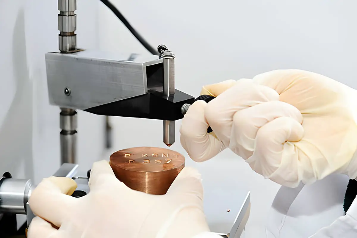
The surface roughness is typically caused by various factors, including the processing method, friction between the tool and the workpiece surface during processing, plastic deformation of the surface metal during chip separation, and high-frequency vibration in the processing system.
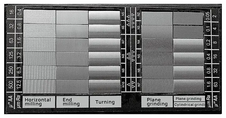
The depth, density, shape, and texture of the marks on the machined surface can vary depending on the specific processing method and material used.
In this article, we will discuss the causes of surface roughness defects and the preventive measures that can be taken to avoid them.
Analysis of common roughness defects
1. Knife mark roughness analysis
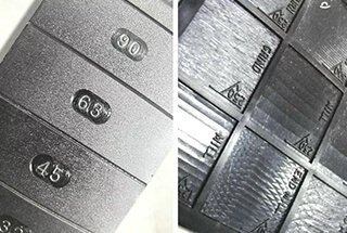
The presence of rough tool marks is usually a result of increasing the cutting feed rate. This is because during the cutting process, the shape of the tool can cause some metal on the processed surface to not be fully cut, leaving behind what is referred to as tool marks.
2. Scale prick phenomenon
The appearance of scale cracks and burrs on the surface during cutting of plastic metal materials is a common occurrence when cutting speed is low and high-speed steel or cemented carbide tools are used. This is referred to as the “scale prick phenomenon.” This is frequently seen in machining processes such as broaching, slotting, and hobbling.
When cutting plastic materials at low speeds with a small rake angle, the chips are often squeezed and cracked, causing a periodic change in the force between the tool and the chip, leading to metal accumulation and resulting in fractures and scales on the machined surface.
3. Scratches and galling
Scratch and galling are also common forms of roughness defects. Examples of these defects include gnawing teeth in gear processing and galling in grinding. By analyzing the evidence left behind by scratches and galling, it is possible to determine the causes and develop measures to address them.
4. Uneven knife pattern
The main cause of an uneven knife pattern is the machine tool, which results in uneven cutting marks on the processed metal surface.
5. High frequency vibration pattern
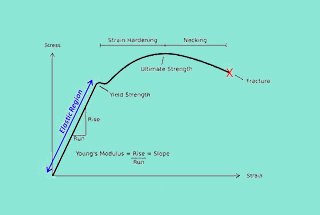
During metal processing, the entire process system can experience vibrations, which can significantly impact the surface roughness of metal parts. This includes the machine tool, cutting tool, and workpiece. Low-frequency vibrations in the process system tend to produce waviness on the workpiece surface, while high-frequency vibrations result in roughness.
The vibrations of the process system can be divided into two types: forced vibration and self-excited vibration. Forced vibration is caused by periodic external forces, while self-excited vibration is produced by the system itself. The most common form of self-excited vibration is cutting-induced vibration.
Troubleshooting Analysis of common roughness defects
1. Knife mark elimination analysis
To improve cutting roughness, it is important to choose an appropriate feed rate. It is recommended to select a smaller feed within the allowed range, however, the feed should not be too small as it can negatively impact the roughness. Additionally, when grinding the tool, increasing the arc radius of the tool tip within the permissible range can positively affect the roughness.
2. Elimination and analysis of scale prick phenomenon
First, control the cutting speed. The occurrence of scale pricking can be attributed to the cutting speed to some extent. If the speed exceeds or falls below the designated range, scale pricking will occur.
Second, adjust the cutting thickness. It is recommended to minimize the cutting thickness as much as possible. An increase in cutting thickness will result in higher pressure between the chip and the front of the tool, leading to more frequent and severe scale pricking.
In addition, using high-quality cutting fluid can effectively prevent the formation of scale pricking. Carefully selecting the cutting tool angle is also an effective solution.
Finally, improve the machinability of the workpiece material. For instance, heating the material before cutting can reduce the scale pricking phenomenon in some cases.
3. Scratch and galling exclusion analysis
If the distribution of scratch and galling marks is consistent, it is usually a result of a problem with the machine tool. In traditional systems such as the spindle box, feed box, and chute box, regular scratch and galling can occur due to shaft bending, poor gear engagement, or damage.
To address this issue, it is important to regularly inspect the machine tool and perform frequent maintenance and repairs.
However, if the scratch and galling marks are inconsistent, it may be related to chips, tools, or cutting fluid. For instance, during deep hole machining, poor chip removal can result in scratch marks on the inner surface.
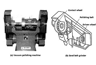
The roughness of the workpiece surface is often caused by abrasive particles and debris falling off during the grinding process, or by using an improper grinding wheel or unclean cutting fluid. To prevent this, it is important to choose the appropriate grinding wheel and maintain clean cutting fluid.
4. Elimination and analysis of unevenness of knife pattern
There are many reasons for the unevenness of the knife pattern, but it is common to see spiral linear traces appearing on the surface of parts when grinding an outer circle. This is often due to a large straightness error in the grinding wheel axis, which emphasizes the importance of carefully selecting and regularly maintaining the grinding wheel.
Another example of uneven knife pattern is caused by the creeping of the machine tool workbench or tool holder, which leads to uneven tool movement. To prevent this from happening, it is crucial to properly maintain and repair the machine tool.
5. Elimination analysis of high frequency vibration ripple
The main way to eliminate high-frequency vibration marks is to identify the source of vibration, eliminate it, or reduce it to an acceptable level. For instance, vibration caused by unbalanced rotation of parts or the transmission system of the machine tool is considered forced vibration.
By locating the source of vibration and repairing the machine tool, the vibration can be eliminated and the vibration marks will disappear.
If the vibration is a result of cutting-induced natural vibration, it occurs throughout the cutting process and requires adjustments to the entire machine tool, tool, and workpiece system. This can involve changing cutting parameters, selecting appropriate tool geometry, properly clamping the tool and workpiece, adjusting machine gaps, and improving the vibration resistance of the machine tool.
Wrap it up
By researching and analyzing common roughness defects in lathe machining, the factors affecting surface roughness during cutting can be identified, and corresponding measures and elimination methods can be determined.
This approach not only helps prevent problems before machining but also enables timely and accurate identification of the root cause of any issues that may arise, leading to prompt resolution. This is of practical importance in enhancing product quality and promoting interchangeable production.