Press Brake Operation Manual (Training PDF)
Attention all mechanics and engineering enthusiasts! Have you ever wondered about the ins and outs of operating a press brake machine? In this blog post, we'll dive into the world…
Selecting the right press brake punch and die is crucial for achieving precise bends and ensuring the longevity of your tools. This guide covers the essential criteria for choosing top punches and lower dies based on factors like bending force, material thickness, and punch shape. By following these guidelines, you’ll avoid common pitfalls such as tool damage and inaccurate bends. Dive in to learn how to optimize your press brake operations and enhance your fabrication quality.

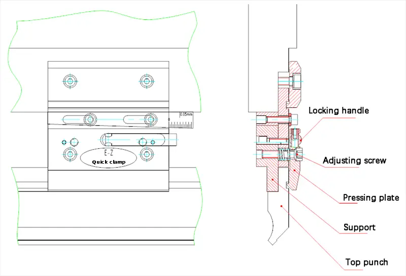
(1) The selection of the top punch should be based on the bending force, and the load of the die should not exceed the limit. A punch with hydraulic clamping requires special customization.
If the user selects special molds, it should be noted that their load differs from that of normal molds. Correct selection should be made to prevent the bending force from exceeding the punch’s load limit, which can cause collapse and cracking.
(2) The shape of the top punch has a significant impact on whether the workpiece can be bent and formed. When programming and selecting the punch, it is crucial to consider the punch’s shape and whether it interferes in the workpiece forming process.
(3) When the mold is programmed into the mold library of the CNC system, the mold’s overall dimensions should be programmed accurately. This ensures that when the NC system automatically calculates the bending process, it can accurately determine whether the mold interferes with the workpiece.
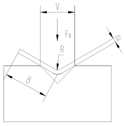
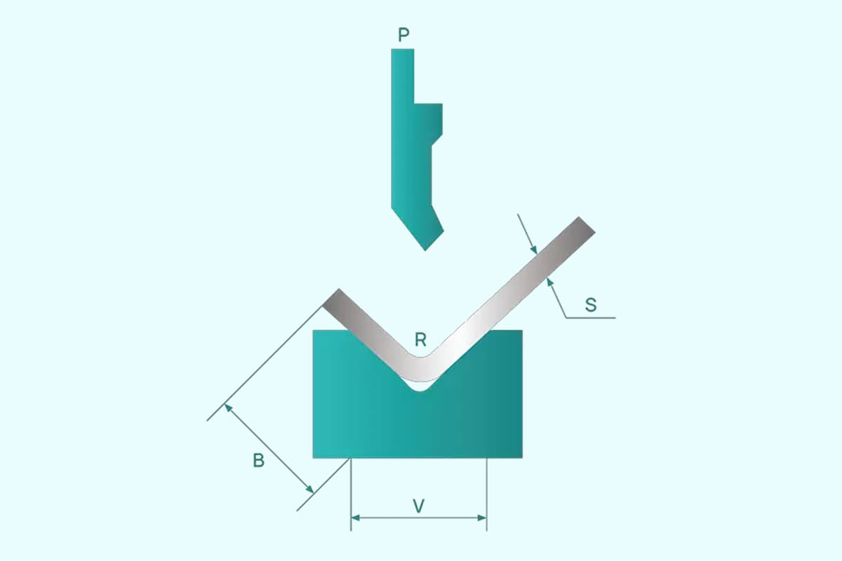
(1) The width of the V-shaped lower die must be determined according to the material’s thickness t, using the following formula:
If t < 3mm, V = (6~8) × t
If t ≥ 3mm, V = (8~12) × t
Additionally, the width of the lower die V can be determined based on the minimum bending width b and the fillet radius r of the bending part to ensure reasonable and scientific die selection.
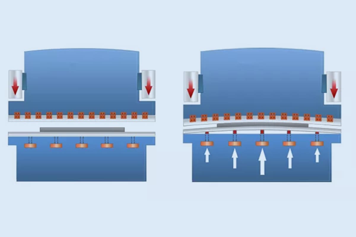
(2) During the bending process, the bending force generated will accumulate on the worktable and act on the die. Therefore, the load that the die can bear should not exceed the limit.
The bending force required per meter (T/m) is given in the bending force table, where the material’s tensile strength is assumed to be 45kg/mm² (450N/mm²) and the lower die opening and plate thickness are predetermined.

Quick reference table of common bending force
When the materials are different, the tensile strength of the material is σ Kg/mm², the required bending force (T/m) per meter can be calculated by the following formula.
F1 = F0· σ/ 450 (T/m)
Note: if the mold is used for forming, the bending force must be 2 to 3 times the normal bending force.
That is:
FP = (2… 3) FB
(FP: forming force FB: free bending force)

As the founder of MachineMFG, I have dedicated over a decade of my career to the metalworking industry. My extensive experience has allowed me to become an expert in the fields of sheet metal fabrication, machining, mechanical engineering, and machine tools for metals. I am constantly thinking, reading, and writing about these subjects, constantly striving to stay at the forefront of my field. Let my knowledge and expertise be an asset to your business.