0° – 180° Bend Allowance Chart for Sheet Metal Bending
Have you ever wondered how sheet metal parts are designed and manufactured with precision? In this blog post, we'll dive into the fascinating world of bend allowance - a crucial…
Ever wondered why your sheet metal projects don’t always turn out as planned? This article explores the common issues encountered during sheet metal bending and forming, from edge irregularities to material cracks. By understanding these problems and their solutions, you can achieve more precise and reliable results in your metalworking projects. Dive in to learn practical tips for overcoming the challenges and enhancing your bending process.

Metal sheet bending and forming is performed on a press brake machine.
To form the workpiece, it is placed on the machine and the brake shoe is lifted by the lifting lever. The workpiece is then positioned correctly, and the brake shoe is lowered onto the workpiece to apply the necessary force for bending and forming.
The bending and forming of the metal is achieved through the application of force to the bending lever on the machine.

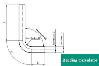
The minimum bending radius of a metal is determined by its ductility and thickness. For aluminum plates, the bending radius should be greater than the thickness of the plate.
During the bending process, springback may occur, so the angle of metal bending should be slightly larger than the desired angle.
Bending of metal plates is performed in a metal processing workshop, and sheet metal processing is a series of processes that include bending, riveting, and welding of metal materials.
In sheet metal processing, various problems may arise during the bending process, and the following are potential solutions to these issues.
Causes of uneven bending edge and unstable dimension:
⑴ Lack of pressing or pre-bending arrangements in the design process;
⑵ Inadequate bending force;
⑶ Unequal wear or stress on the round corners of male and female dies;
⑷ Too small height dimension.
There are four solutions:
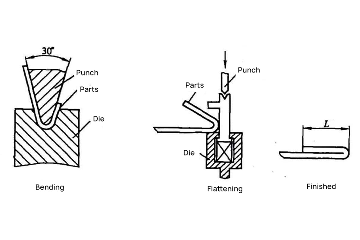
⑴ Design the crimping or pre-bending process.
⑵ Increase the pressing force.
⑶ Ensure that the gap between the male and female dies is even and the rounded corners are polished.
⑷ Ensure that the height dimension meets the minimum limit dimension.
Causes of external surface scratch after workpiece bending:
⑴ The surface of the raw materials is rough.
⑵ The bending radius of the punch is insufficient.
⑶ The bending clearance is inadequate.
Solutions mainly include:
⑴ Enhance the surface finish of the male and female dies.
⑵ Increase the bending radius of the punch.
⑶ Adjust the bending clearance.
Reasons for cracks in bending angle:
⑴ The inner bending radius is insufficient.
⑵ The grain direction of the material is aligned with the bending curve.
⑶ The burr on the blank faces outward.
⑷ The metal’s plasticity is poor.
Solutions mainly include:
⑴ Increase the bending radius of the punch.
⑵ Alter the blanking layout.
⑶ Ensure that the burr is on the fillet of the part.
⑷ Perform annealing or use softer materials.
Causes of hole deformation caused by bending:
When employing elastic bending and positioning with holes, the outer side of the bending arm may be distorted due to friction between the female die surface and the outer surface of the workpiece, leading to deformation of the positioning holes.
Solutions mainly include:
⑴ Implement shaped bending.
⑵ Increase the pressure of the ejector plate.
⑶ Place a grid with indentations on the ejector plate to enhance friction and prevent slipping of the parts during bending.
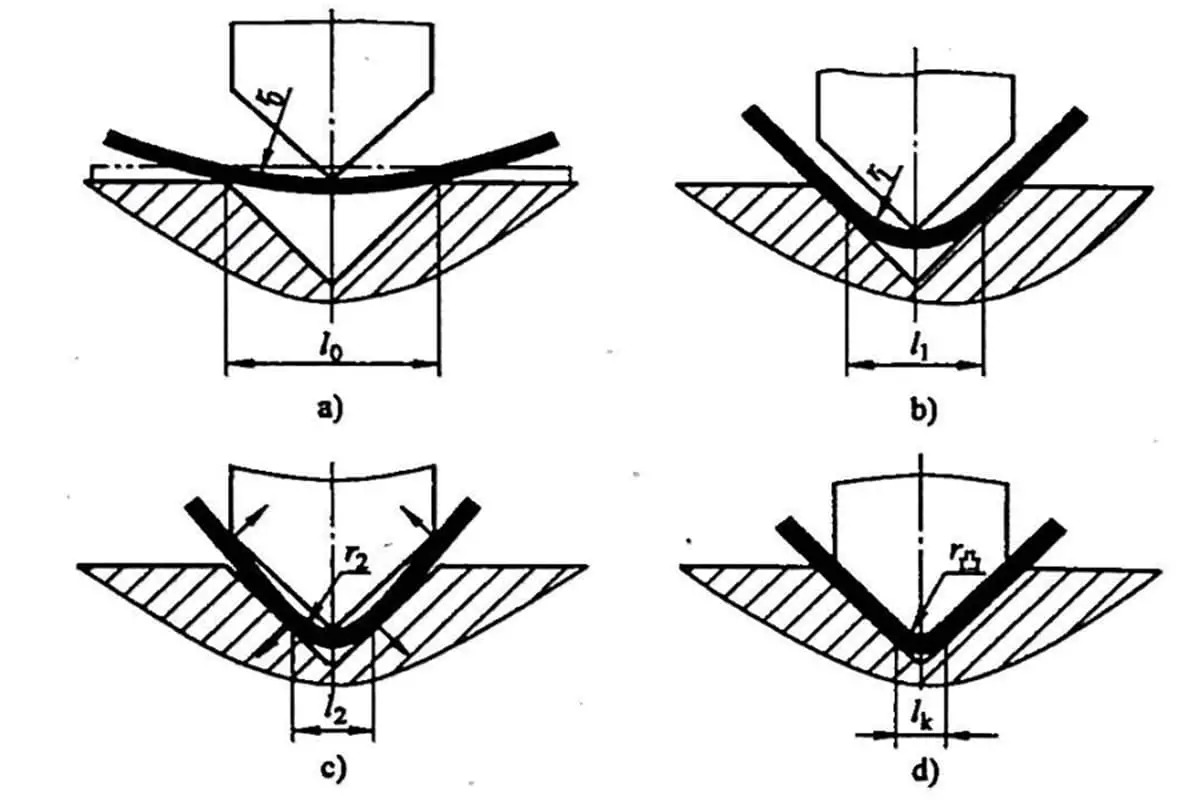
Reasons for thinning of extruded material on the curved surface:
⑴ The female die fillet is too small;
⑵ The clearance between male and female dies is too small.
Solutions mainly include:
⑴ Increase the fillet radius of the female die;
(2) Correct the clearance between male and female dies.
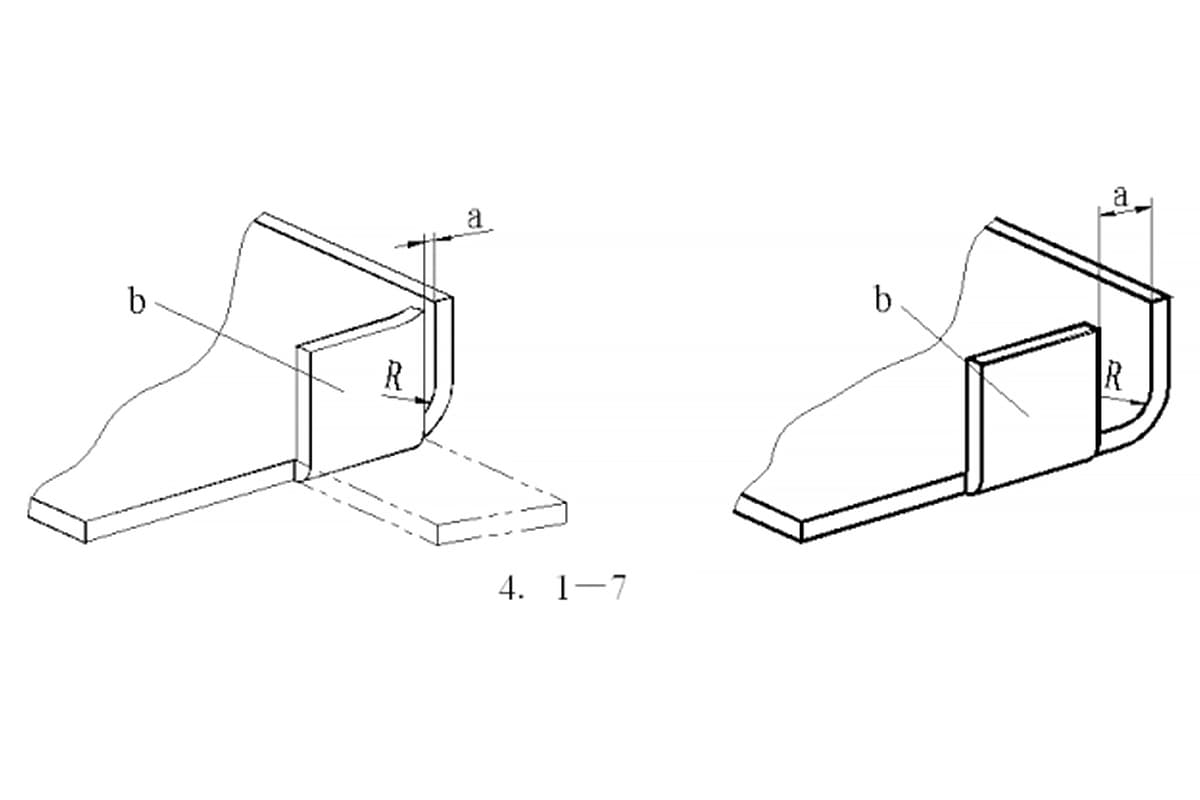
The reasons for the bulge or unevenness of the end face of the part are:
During bending, the outer surface of the material undergoes tension in the circumferential direction, leading to shrinkage deformation, while the inner surface experiences pressure in the circumferential direction, causing elongation deformation. As a result, the end face along the bending direction will experience a bulging effect.
Solutions mainly include:
⑴ Ensure that the male and female dies have adequate pressure during the final stage of stamping.
⑵ Align the fillet radius of the female die with the fillet of the workpiece.
⑶ Enhance the added process.
The reasons for the uneven bottom of the concave part are:
⑴ The material has unevenness.
⑵ The contact area between the top plate and the material is limited or the jacking force is inadequate.
⑶ The female mold lacks a jacking device.
Solutions mainly include:
(1) Leveling materials;
⑵ Adjust the jacking device to increase the jacking force;
⑶ Add jacking device or correct;
⑷ Add shaping process.
The causes of the axial misalignment of the two opposite holes on both sides after bending are:
The material’s springback altering the bending angle and causing a shift in the center line.
The main solutions are:
Enhance the correction process and improve the design of the bending die to minimize the material’s springback.
Reasons why the dimensional accuracy of hole position cannot be guaranteed after bending:
⑴ The developed dimension of the parts is wrong;
⑵ Caused by material rebound;
(3) Unstable positioning.
Solutions mainly include:
⑴ Accurately calculate the blank size;
⑵ Add correction process or improve the forming structure of bending die;
⑶ Change the process processing method or increase the process positioning.
The reason why the bending curve is not parallel to the center line of the two holes is:
When the bending height is less than the minimum bending limit height, the bending part will expand.
The solution is:
Increase the height and size of the bending parts and improve the process methods of the bending parts.
The widthwise deformation and the bow-shaped deflection of the bent part in the width direction are caused by the uneven stretching and contraction in the width direction of the workpiece, leading to twisting and deflection.
Solutions mainly include:
⑴ Increase bending pressure;
⑵ Add correction process;
⑶ Ensure that there is a certain angle between the material grain direction and the bending direction.
The reasons for the downward deflection of the products with notches are as follows:
The notch makes the two straight edges open to the left and right, and the bottom of the workpiece deflects.
Solutions mainly include:
⑴ Improve the structure of parts;
⑵ Increase the process allowance at the cut to connect the cuts and then cut off the process allowance after bending.

As the founder of MachineMFG, I have dedicated over a decade of my career to the metalworking industry. My extensive experience has allowed me to become an expert in the fields of sheet metal fabrication, machining, mechanical engineering, and machine tools for metals. I am constantly thinking, reading, and writing about these subjects, constantly striving to stay at the forefront of my field. Let my knowledge and expertise be an asset to your business.