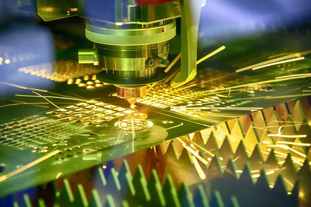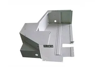
Sheet Metal Joining Process: The Ultimate Guide
Have you ever wondered how sheet metal parts are joined together to create complex structures? In this blog post, we'll explore the fascinating world of sheet metal joining techniques. As…
How does a flat metal sheet transform into complex shapes and structures? This blog post delves into the intricate processes of sheet metal forming, including partial shearing, bridge drawing, and hole extrusion. Discover the methods and tools used to create precise and functional metal components. By the end, you’ll understand the critical techniques behind everyday metal products and their applications.
1. Definition:
Applying a certain pressure in a direction perpendicular to the surface of the material to cause the material to flow in the direction of the force, resulting in a forming effect.
2. Functions:
Positioning, such as for welding with half-cutting.
Riveting, such as for riveting electrostatic conductive rails.
3. Processing methods:
NCT: using regular tool combinations (downward half-cutting) or specially developed tools for processing.
Pre-processing: special half-cutting can be used to achieve plate pressing and easy die realization (when the batch size is not large).
4. Precautions:
The height of half-cutting is best not to exceed 0.6T.
1. Function:
Used for positioning by the top surface, sometimes with a punch mark on it.
Used for limiting by the side edge.
Used for passing binding wire through the hole.
2. Processing methods:
Machining with NCT-specific tools.
Easy mold forming by pre-processing.
Easy mold forming by folding machine.
Mold forming.
1. Function:
Counterbore hole for use with countersunk screws.
Countersink hole for use with flat head screws.
Rivet nut hole for use with expanding rivet nuts.
2. Processing methods:
Machining with NCT-specific tools.
Machining with a drilling machine.
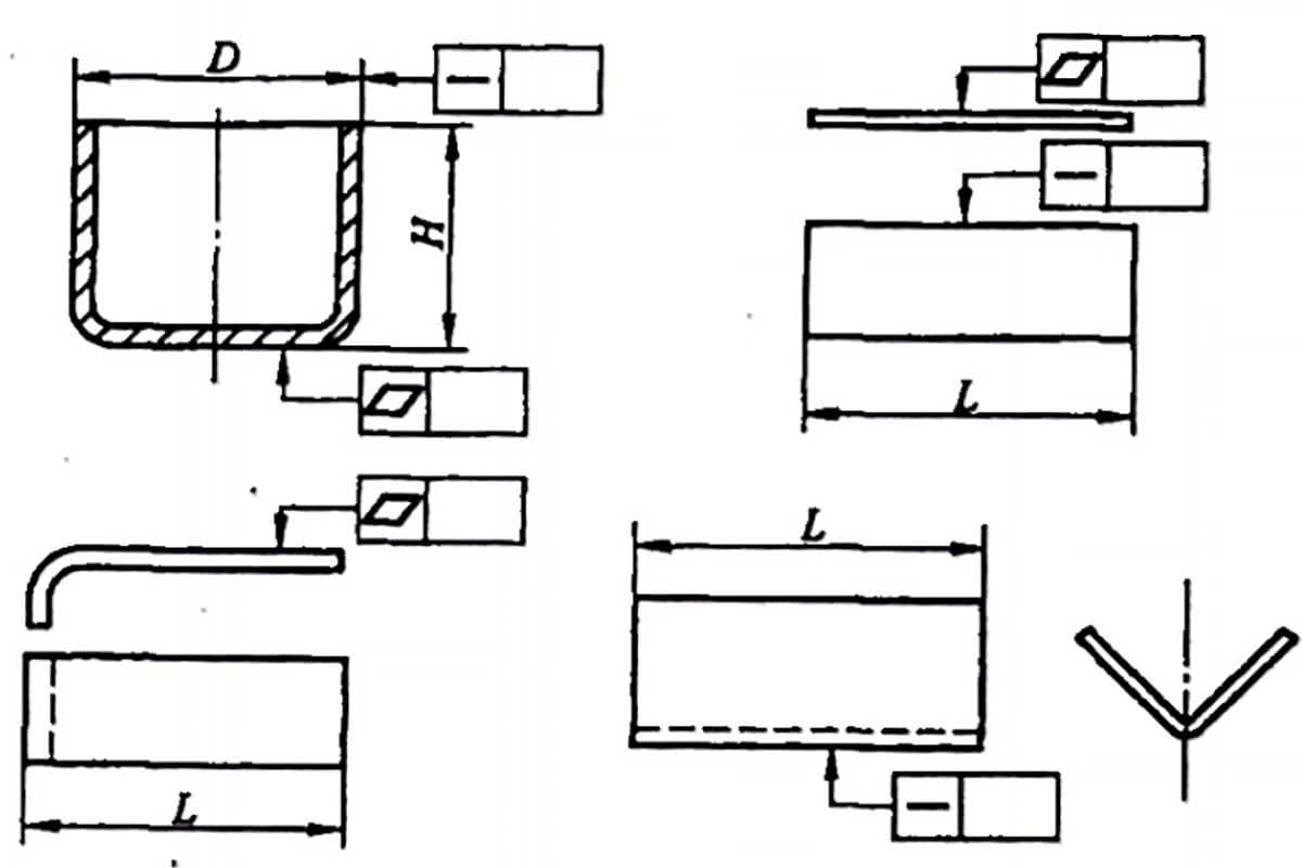
1. Structure description:
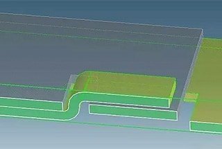
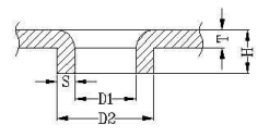
Hole extrusion & embossing is a process of vertically punching a hole with a certain inner diameter, outer diameter, and height on a metal sheet. It is mainly used for riveting, passing through holes, tapping, and other purposes.
There are two types of punching: general punching and special-shaped punching.
The forming diagram is shown below:
2. Processing methods:
General punching uses a shared mold for processing, while special-shaped punching requires the design of a specific die.
3. Mold processing methods:
(1) Shared molds for general punching are shown in the following table:
Shared molds for general punching.
| Upper Die for Punching Hole.(1) | Die number | Shared mold 001 | 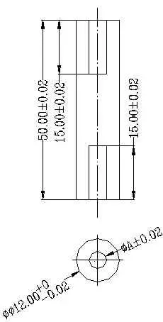 | Description: Clamping outer diameter is Φ12.00. | ||
| “A” value | 1.0~7.9 | |||||
| Inter-grade Size | 0.1 | |||||
| Quantity (Grade X pieces/grade). | 70X4=280 | |||||
| Upper Die for Punching Hole.(2) | Die number | Shared mold 004 | 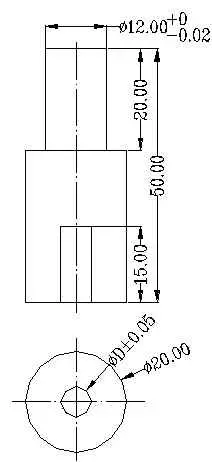 | Description: Clamping outer diameter is Φ12.00. | ||
| “D” value | 8.0~12.0 | |||||
| Inter-grade Size | 0.2 | |||||
| Quantity (Grade X pieces/grade). | 21X3=63 | |||||
| Upper Die for Punching Hole.(3) | Die number | Shared mold 005 | 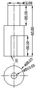 | Description: Clamping outer diameter is Φ12.00. One end at R position is chamfered, the other end is not chamfered. | ||
| “E” value | 12.5~20.0 | |||||
| Inter-grade Size | 0.5 | |||||
| Quantity (Grade X pieces/grade). | 16X2=32 | |||||
| Lower Die for Punching Hole(1) | Die number | Shared mold 010 |  | Description: Used together with the punch holder (1). The maximum outer diameter is Φ8.00. | ||
| “F” valve | 1.0~6.0 | |||||
| Inter-grade Size | 0.5 | |||||
| Quantity (Grade X pieces/grade). | 10X2=20 | |||||
| Lower Die for Punching Hole(2) | Die number | Shared mold 011 | 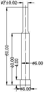 | Description: Used together with the punch holder (1). The maximum outer diameter is Φ8.00. | ||
| “F” value | 1.0~6.0 | |||||
| Inter-grade Size | 1.0 | |||||
| Quantity (Grade X pieces/grade). | 6X1=6 | |||||
| Lower Die for Punching Hole(3) | Die number | Shared mold 012 | 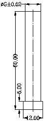 | Description: Used together with the punch holder (2) when G value is 8.0 and 10.0. The maximum outer diameter is Φ12.00. | ||
| “G” value | 8.0~12.0 | |||||
| Inter-grade Size | 2.0 | |||||
| Quantity (Grade X pieces/grade). | 9+5+3=17 | |||||
| Lower Die for Punching Hole(4) | Die number | Shared mold 013 | 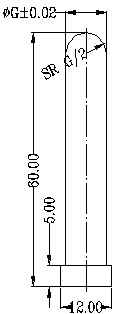 | Description: Used together with the punch holder (2) when G value is 8.0 and 10.0. The maximum outer diameter is Φ12.00. | ||
| “G” value | 8.0~12.0 | |||||
| Inter-grade Size | 2.0 | |||||
| Quantity (Grade X pieces/grade). | 3X1=3 | |||||
| Punch Holder(1) | Die number | Shared mold 002 |  | Description: Used together with the lower die for punching holes. Clamping outer diameter is Φ12.00. | ||
| “B” value | 3.0~6.0 | |||||
| Inter-grade Size | 1.0 | |||||
| Quantity (Grade X pieces/grade). | 4X5=20 | |||||
| Punch Holder(2) | Die number | Shared mold 003 |  | Description: Used together with the lower die for punching holes. Clamping outer diameter is Φ12.00. | ||
| “C” value | 8.0~10.0 | |||||
| Inter-grade Size | 2.0 | |||||
| Quantity (Grade X pieces/grade). | 2X1=2 | |||||
4. Parameters Table for Punching Marking Holes
Metric System:
| Tapping Marking Hole Model | Thread Diameter | Punching Hole Inner Diameter | Requirements for Punching Hole Inner Diameter | |
| MIN | MAX | |||
| M1*0.25 | 0.75 | 0.78 | 0.729 | 0.785 |
| M1.1*0.25 | 0.85 | 0.88 | 0.829 | 0.885 |
| M1.2*0.25 | 0.95 | 0.98 | 0.929 | 0.985 |
| M1.4*0.3 | 1.1 | 1.14 | 1.075 | 1.142 |
| M1.6*0.35 | 1.25 | 1.32 | 1.221 | 1.321 |
| M1.7*0.35 | 1.35 | 1.42 | 1.321 | 1.421 |
| M1.8*0.35 | 1.45 | 1.52 | 1.421 | 1.521 |
| M2*0.4 | 1.6 | 1.65 | 1.567 | 1.679 |
| M2.2*0.45 | 1.75 | 1.83 | 1.713 | 1.838 |
| M2.3*0.4 | 1.9 | 1.97 | 1.867 | 1.979 |
| M2.5*0.45 | 2.1 | 2.13 | 2.013 | 2.138 |
| M2.6*0.45 | 2.2 | 2.23 | 2.113 | 2.238 |
| M3*0.5 | 2.5 | 2.59 | 2.459 | 2.599 |
| M3.5*0.6 | 2.9 | 3.01 | 2.85 | 3.01 |
| M4*0.7 | 3.3 | 3.39 | 3.242 | 3.422 |
| M4.5*0.75 | 3.8 | 3.85 | 3.688 | 3.878 |
| M5*0.8 | 4.2 | 4.31 | 4.134 | 4.334 |
| M6*1 | 5 | 5.13 | 4.917 | 5.153 |
| M7*1 | 6 | 6.13 | 5.917 | 6.153 |
| M8*1.25 | 6.8 | 6.85 | 6.647 | 6.912 |
| M9*1.25 | 7.8 | 7.85 | 7.647 | 7.912 |
| M10*1.5 | 8.5 | 8.62 | 8.376 | 8.676 |
| M11*1.5 | 9.5 | 9.62 | 9.376 | 9.676 |
| M12*1.75 | 10.3 | 10.40 | 10.106 | 10.441 |
Imperial System:
| Tapping Marking Hole Model | Thread Diameter | Punching Hole Inner Diameter | Requirements for Punching Hole Inner Diameter | |
| MIN | MAX | |||
| 1-64 | 1.55 | 1.57 | 1.425 | 1.582 |
| 2-56 | 1.8 | 1.86 | 1.695 | 1.871 |
| 3-48 | 2.1 | 2.14 | 1.941 | 2.146 |
| 4-40 | 2.3 | 2.36 | 2.157 | 2.385 |
| 5-40 | 2.6 | 2.69 | 2.487 | 2.697 |
| 6-32 | 2.8 | 2.86 | 2.642 | 2.895 |
| 8-32 | 3.4 | 3.52 | 3.302 | 3.530 |
| 10-24 | 3.9 | 3.91 | 3.683 | 3.962 |
| 12-24 | 4.5 | 4.57 | 4.344 | 4.597 |
| 1/4-20 | 5.1 | 5.25 | 4.979 | 5.257 |
| 5/16-18 | 6.6 | 6.72 | 6.401 | 6.731 |
| 3/8-16 | 8 | 8.15 | 7.798 | 8.153 |
| 7/16-14 | 9.4 | 9.5 | 9.144 | 9.550 |
| 1/2-13 | 10.8 | 11.0 | 10.592 | 11.023 |
| 9/16-12 | 12.2 | 12.3 | 11.989 | 12.446 |
| 5/8-11 | 13.6 | 13.8 | 13.386 | 13.868 |
| 3/4-10 | 16.5 | 16.8 | 16.307 | 16.840 |
| 7/8-9 | 19.5 | 19.6 | 19.177 | 19.761 |
| 1-8 | 22.2 | 22.5 | 21.971 | 22.606 |
| 1 1/8-7 | 25 | 25.2 | 24.638 | 25.349 |
Note:
1. Use cutting tap.
2. The punching hole height should not be less than 3 times the pitch.
3. When the material thickness is less than 0.5mm, the wall thickness of the punching hole is the same as the material thickness. When the material thickness is between 0.5mm and 0.8mm, the wall thickness of the punching hole is 0.7 times the material thickness. When the material thickness is greater than or equal to 0.8mm, the wall thickness of the punching hole is 0.65 times the material thickness.
Shim is a common forming method with fixed shape and function. The size of the shape has little effect on its function, and its forming method mainly relies on shared molds.
Now we will introduce the function and forming method of shim:
I. Shim structure and function:
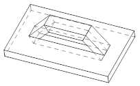
Basic types:
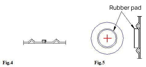
There are generally two basic types of shims (Figure 1) (Figure 2), and the structure of the shim is shown in Figure 3. There are also several shapes with protrusions in a hemispherical form.


Function analysis:
It is a circular punching shape, and its main function is to use its punching shape to support the chassis or fix the motherboard, to avoid the bottom contacting the ground completely, so their height is consistent.
If it is a chassis shim, the shape is generally like Figure 4; if it is a motherboard shim, the shape is like Figure 5.
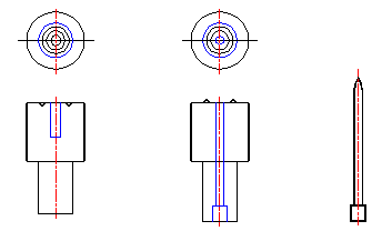
It generally has punching marks on top because the chassis shim mainly serves as a support function and generally has a rubber pad attached underneath, and Figure 5 generally only has four.
However, the motherboard shim not only serves as a support function but also a fixing function, so it has punching marks on top.
Note that the punching mark height is less than the shim height, and the number corresponds to the motherboard.
II. Forming methods for shims
Due to the fixed shape of shims, their size has little effect on their function as long as the height and center position are ensured. Therefore, several specifications of shared molds have been designed.
In the case of similar sizes (±1mm), a similar specification of shared mold can be used instead. For shapes with greater differences and no similar specifications of shared molds, the method of designing a pressure plate mold can be used for forming.
The shim molds for sample production are generally divided into pressure plate molds and shared molds.
Pressure plate molds have a fast forming speed and can form multiple shims at once, but they are not flexible and can only be used for forming a specific workpiece.
Shared molds use the common characteristics of shims and can be repeatedly used to form shims with the same specifications, reducing production costs.
Pressure plate mold (pre-processing)
Below is an example of a shim (NKB83001A), and note that the material for a circular block can be obtained directly from the waste material of the previous ring block.
The module stacking diagram is shown in Figure 9.

Shared mold (folding machine)
The design method of using a folding machine mold increases the forming height by 0.2 to account for rebound, and a positioning hole is added to the center of the upper mold.
A positioning punch is designed to be placed in the positioning hole, and a center point is marked for positioning the shim, which matches the positioning punch.
The schematic diagram of the mold is shown below (Figure 11).
Currently, there are four types of shared mold specifications for shims (see Table 1).
There are four sets of molds, with the first three types forming the shape shown in Figure 2 and the fourth set forming the shape shown in Figure 1, as shown in Table 2.
The upper and lower mold punches are fixed to the upper and lower mold fixtures, and the fixtures are fixed to the upper and lower slots.
NCT tool processing
See NCT tool table.
III. Appendix.
Table 1: Common shared mold specifications
| Serial number | Unit of use | Corresponding value | Remarks | ||
| Outer diameter (D1). | Inner diameter (D). | Height (H) | |||
| 1 | Folding machine | 28 | 20 | 2.0 | |
| 2 | 32 | 25 | 1.8 | ||
| 3 | 26.5 | 12.5 | 2.8 | ||
| 4 | 12.5 | 6.5 | 1.0 | ||
| 1 | NCT | 26.72 | 13.28 | 2.5 | T=1.0 |

Table 2: Forms and specifications of shared molds
| Upper mold | Lower mold | |
| First set |  |  |
| Second set |  |  |
| Third set |  |  |
| Fourth set |  | 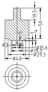 |

As the founder of MachineMFG, I have dedicated over a decade of my career to the metalworking industry. My extensive experience has allowed me to become an expert in the fields of sheet metal fabrication, machining, mechanical engineering, and machine tools for metals. I am constantly thinking, reading, and writing about these subjects, constantly striving to stay at the forefront of my field. Let my knowledge and expertise be an asset to your business.