0° – 180° Bend Allowance Chart for Sheet Metal Bending
Have you ever wondered how sheet metal parts are designed and manufactured with precision? In this blog post, we'll dive into the fascinating world of bend allowance - a crucial…
Have you ever wondered why some locomotive parts can’t be made directly from design drawings? This article explores the fascinating world of sheet metal bending, highlighting common challenges and innovative solutions. Dive in to learn how engineers overcome these hurdles to create precise, high-quality parts.
In the production of locomotive parts using sheet metal bending, many workpieces cannot be directly produced according to the design drawings. As a result, it becomes necessary to add stretchers, positioning, or special bending sets during blanking and remove them after bending to achieve the desired outcome.
This post primarily addresses the process-related issues and solutions in bending processing, which is divided into three sections.
The first section provides an overview of bending processing methods, the second section discusses potential process-related problems and their corresponding solutions in bending processing, and the final section summarizes the key points.
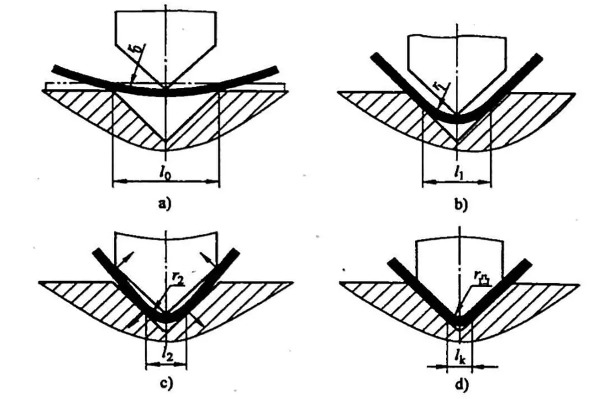
Bending is essentially a cold deformation process used to shape plates into specific shapes. It is a pressure processing method performed at room temperature. Bending can be used on a variety of materials including metal, non-metallic, and composite materials.
During this process, the workpiece is processed by a bending die and hydraulic press brake. The dimensional accuracy of bending parts is ensured by upper and lower dies and bending equipment. The process involves applying bending force to the upper die on the sheet metal, generating a reaction force at the support point of the lower die, and forcing the sheet metal to deform, creating a bending moment.
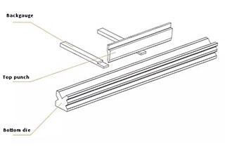
The final bending angle of the sheet metal is determined by the depth of the upper die into the lower die. Figure 1 illustrates the main working parts of the NC press brake, including the rear stop, upper die, and lower die.
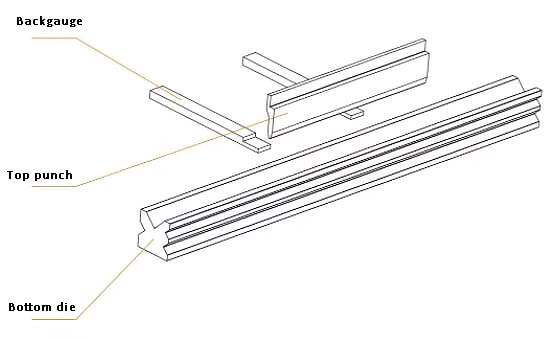
Fig. 1 Main working parts of bending machine
The back gauge is an operational component that regulates the positioning of the bending line.
The upper and lower dies are utilized to manage the bending angle and inner radius of the workpiece.
The qualification of the workpiece is primarily determined by these three parts.
In the production of locomotive parts, many bending workpieces cannot be directly produced according to the design drawings. Therefore, it becomes necessary to add some stretchers, positioning, or special molds during blanking, which can be removed after bending to achieve the desired product.
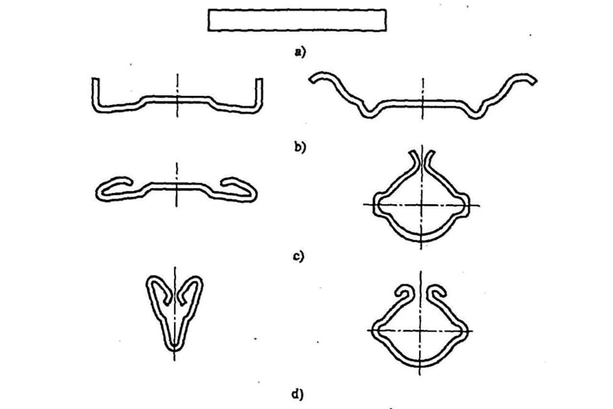
The typical situations that require process stretchers are summarized below.
According to Fig. 2, the insufficient material on one side of the workpiece prevents the placement of the material on the lower die, resulting in the collapse of some structures during bending. This clearly does not meet the design requirements.
Fig. 2 Collapsible edge structure
As shown in the structural detail in Fig. 3, generally, when this angle α is less than 50°, there will be a problem that can not be folded. Process measures must be taken to avoid it and ensure that the workpiece is qualified.
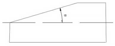
Fig. 3 Workpiece with easy collapse edge
Fig. 4 shows the general process lacing scheme, and the double dotted line part is the set process lacing.
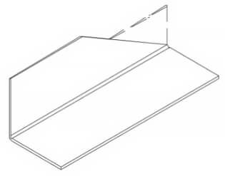
Fig. 4 Process reinforcement scheme
Fig. 5 shows the detailed drawing of process lacing.

Fig. 5 Process structure detail of workpieces easy to collapse
If the length of the workpiece is sufficient for material retention and positioning after the bending process, it is typically set to L ≥ 0.6mm (where V is the opening size of the lower die).
It is essential to ensure that the sheet can be placed on the lower die and extend beyond the edge of the die by at least 3mm.
If the length of the workpiece is insufficient, a tie bar is generally added to match the width of the original structure of the workpiece. This approach not only resolves folding issues but also ensures precise positioning.
As depicted in Figure 6, some workpieces designed for positioning have sharp corners or their straight edges, which are meant for positioning, are too short. This makes it challenging to locate the bending line accurately during the bending process.
To achieve precise positioning of the bending line, a process structure needs to be added.
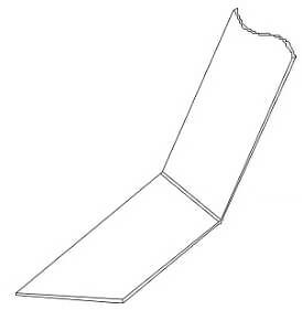
Fig. 6 Bending line positioning
Solution: Fig. 7 and fig. 8 are two process stretching schemes to solve the difficult positioning of the bending line, in which the double dotted line is the process stretching.

Fig. 7 Scheme I for solving the difficulty of bending line positioning

Fig. 8 Solution to the difficult positioning of bending line figure 2
Fig. 9 shows the processing diagram of scheme 1. By adopting this scheme, the workpiece can be well-positioned.

Fig. 9 Processing diagram of scheme I
Fig. 10 shows the processing schematic diagram of scheme 2. In this scheme, wing plates are added on both sides of the workpiece, which can ensure that the processed workpiece meets the design requirements.

Fig. 10 Processing diagram of scheme II
Solution for easy deformation of the workpiece
According to Fig. 11, the laser cutting machine blanks the workpiece when its thickness is low.
It’s worth noting that laser cutting falls under the category of melting cutting, generating high temperatures.
However, in case of the workpiece structure depicted in the figure, it might undergo deformation, resulting in inaccurate bending positioning. To avoid such issues, appropriate process measures must be taken.

Fig. 11 Easily deformed structure
Solution: as shown in Fig. 12, for the large gap shown in the figure, the workpiece is easy to deform during handling or positioning, resulting in inaccurate bending positioning.
Generally, the process stretching shown in the figure will be added.
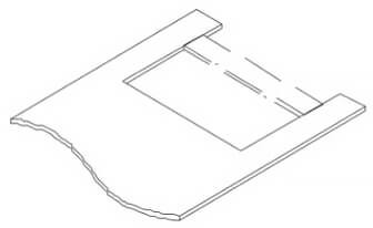
Fig. 12 Adding process stretchers
Incorporating stretchers into the notch can enhance the workpiece’s overall stiffness and prevent deformation.
Following the completion of the bending process, utilize manual plasma to cut the stretchers.
For large and lengthy workpieces, it is necessary to retain the stretchers to prevent deformation during lifting or installation in the subsequent process. The stretchers should be removed only after welding in the next process.
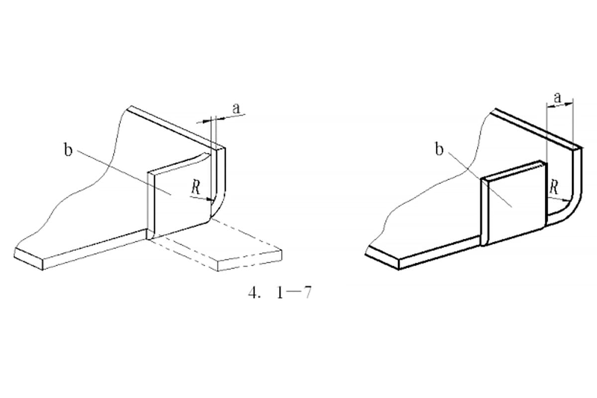
As depicted in Figure 13, the groove width of the workpiece is too narrow, causing it to interfere with the upper die during bending. This, in turn, leads to workpiece deformation, which makes it impossible to complete the processing, and the final workpiece size fails to meet the requirements specified in the drawing.
To address this issue, we recommend the solution depicted in Figure 14. Before bending the workpiece, it is advisable to reverse bend a certain angle in the middle of the workpiece. Subsequently, the workpiece can be bent according to the drawing specifications.

Fig. 13 Interference between the workpiece and upper die

Fig. 14 After pre-bending, the upper die no longer interferes with the workpiece
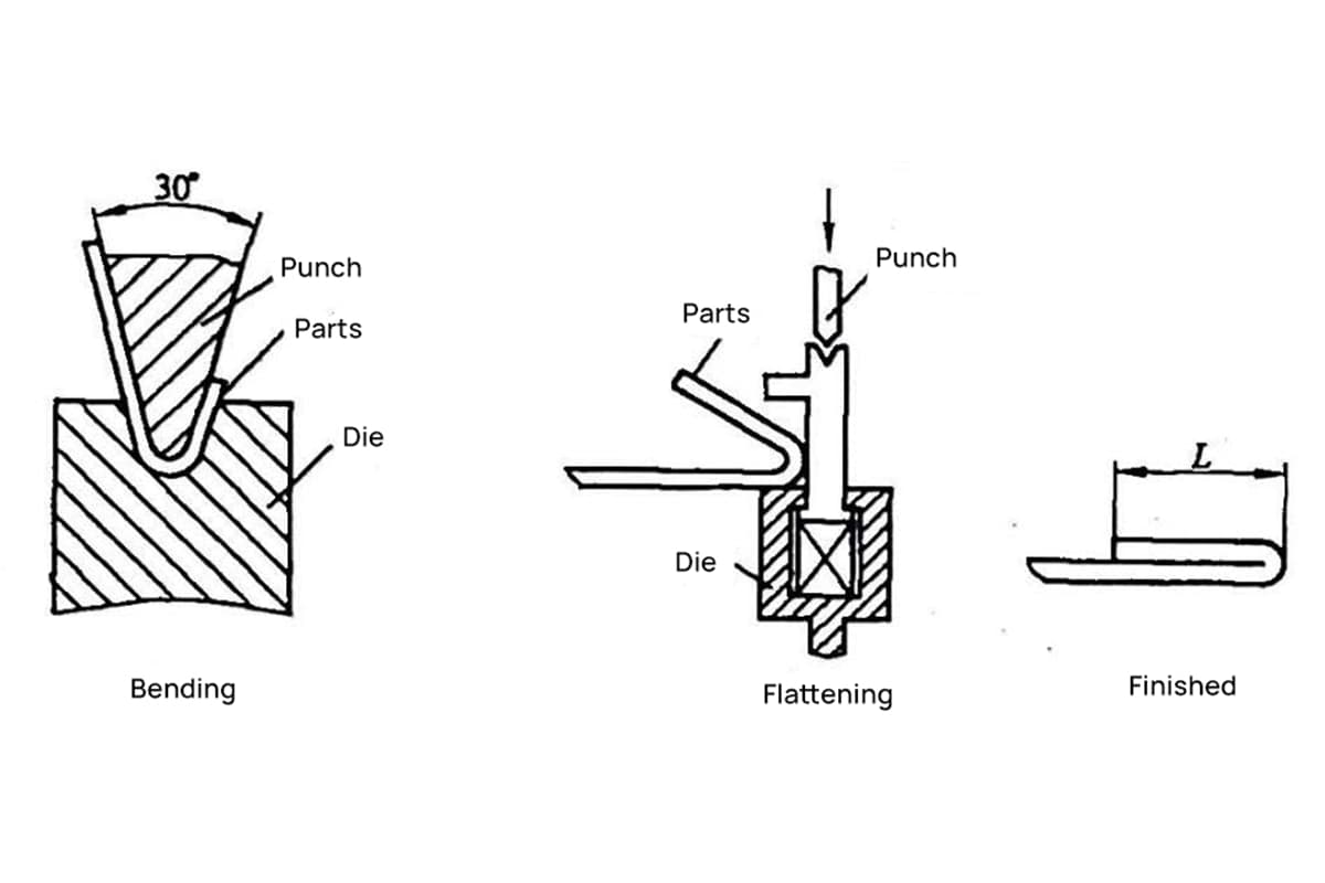
After the workpiece is folded, press the pre-folded bend with a flattening die (Fig. 15), and ensure the flatness and size requirements of the workpiece.

Fig. 15 Point pressing and flattening with flattening die at pre bend
Based on Fig. 16, the developed length measures 2500mm, the groove width is 100mm, and the leg height is 64mm. These parameters are entered as per the process card requirements. To proceed, an upper die with R8 V60° and a height of 134mm is chosen, and a lower die with No. V07, featuring an opening of 35mm and a depth of 65mm is selected.
Various bending deflection parameters are then input, and the workpiece is placed on the worktable to perform the necessary bending. However, during the bending process, an issue arises. As the upper die of R8 gooseneck is thick and the gooseneck is too small, the first bending edge interferes with the mold when the second side’s unilateral bending is fast to reach 90°. This interference makes it impossible to ensure the bending angle.
Attempting to force the bending can cause several problems, including deformation of the workpiece, damage to the mold, and non-conformance of the workpiece’s size to the drawing.
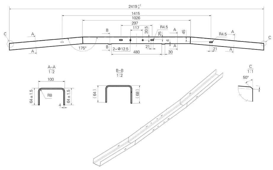
Fig. 16 Workpiece groove width is too narrow to be bent
After conducting on-site research and studying the parameters of the machine tool, as well as observing the existing mold, we discovered that the gooseneck opening of the upper mold R6 is larger than necessary. However, after testing, we found that it meets the process requirements.
Following the above workflow, we carried out synchronous operations without any interference between the mold and the workpiece, which met the requirements.
After multiple adjustments to the Y-axis and X-axis parameters, the dimensions of each point on the workpiece met the drawing requirements.
Upon identification, we confirmed that it meets the process requirements.
Process stretching and crack stop grooves are indispensable in sheet metal bending and are crucial for ensuring workpiece quality and processing efficiency.
It is worth noting that while ensuring product quality, the flexible application of process stretching and crack stop grooves, along with reducing plate waste rates, are also worth discussing.

As the founder of MachineMFG, I have dedicated over a decade of my career to the metalworking industry. My extensive experience has allowed me to become an expert in the fields of sheet metal fabrication, machining, mechanical engineering, and machine tools for metals. I am constantly thinking, reading, and writing about these subjects, constantly striving to stay at the forefront of my field. Let my knowledge and expertise be an asset to your business.