Welding Spatter: Causes and Effective Control Methods
Ever wondered why welding sometimes results in those annoying spatter bursts? These tiny molten metal droplets can ruin your work and cause safety issues. In this article, we explore the causes of welding spatter and share practical methods to control it. You’ll learn about common factors like electrode quality, welding parameters, and surface cleanliness. By the end, you’ll have actionable tips to minimize spatter, ensuring smoother, safer welding operations. Dive in to enhance your welding skills and improve your results.
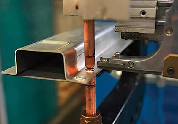
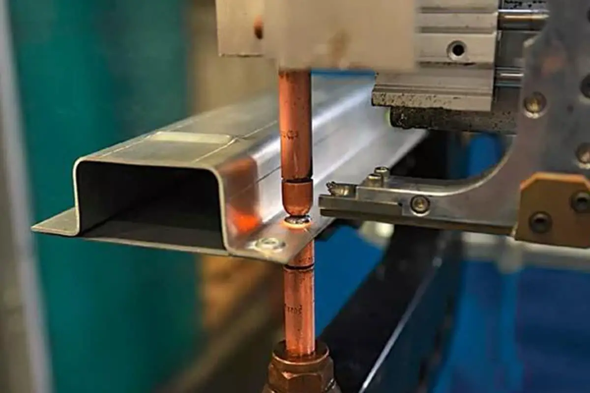
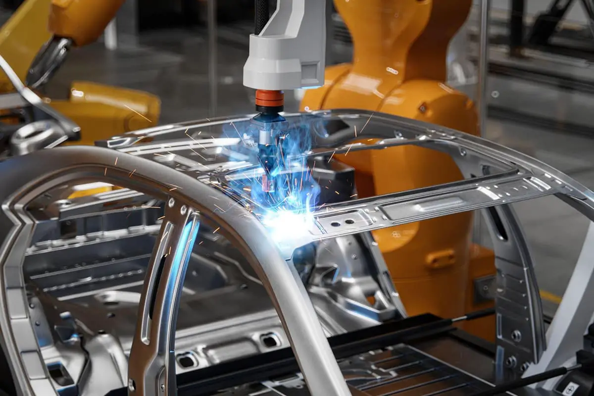
Have you ever considered the following issue? During our welding operations, while the arc light flashes and the welding sparks produce brilliance, we operators are constantly being scorched. What could be the cause of this phenomenon?
1. The principle of resistance spot welding
Welding is a process that uses heating, pressure or both, with or without filler material, to achieve atomic bonding between two separate metal surfaces, forming a permanent connection.
The essence of welding:
The reason why solids such as metals can maintain a fixed shape is because the distance (lattice) between their internal atoms is very small, and they form strong binding forces between atoms.
Unless enough external force is applied to break these bonds between atoms, a solid metal will not deform or separate into two pieces.
To connect two separate metal components together, from a physical point of view, it is necessary to bring the atoms on the connection surface of these two components closer to each other to the distance between metal lattice.
Resistance welding is a method of using electric current to heat up and melt or plasticize the objects being welded by clamping them between electrodes and passing current through the contact surface and surrounding areas of the object being welded.
Basic principle of resistance welding:
The heat generated during welding and factors affecting heat generation, the amount of heat generated during spot welding is determined by the Joule’s law according to the following formula:
Total heat: Q = I2RT
Q – heat generated (joules),
I – welding current (ampere),
R – electrode resistance (ohm),
T – welding time (seconds).
Where R = 2Rpieces + Rcontacts + 2Relectrodes (as shown in figure 1).
Figure 1 Resistance distribution during spot welding.
Figure 2 Relationship between contact resistance and temperature
The heat generated by the contact resistance Rcontacts + 2Relectrodes accounts for about 10% of the total heat, while the heat generated by the internal resistance 2Rpieces of the welded joint accounts for about 90% of the total heat. The highest temperature is always at the center of the welding area, where the fusion zone is formed.
Rcontacts are harmful to welding and are the main cause of spatter and burn-through at the weld point. During welding, the metal on the contact surface reaches the welding temperature first.
As the temperature continues to rise, the contact resistance disappears, and the resistance heat of the plate itself continues to act, forming a weld point that is evenly distributed on both sides of the contact surface.
Relectrodes are harmful to welding because they overheat the plate and reduce the electrode life or even burn out the electrode and the plate surface.
In spot welding, it is impossible for the entire surface of the workpiece to make contact, so there is contact resistance. The number of contact points and the size of the contact area depend on the hardness of the metal material, the smoothness of the surface processing, and the pressure applied to both ends of the workpiece.
Obviously, the softer the workpiece material, the smoother the surface, and the greater the pressure, the smaller the contact resistance.
For low carbon steel, when the temperature exceeds 6000C, the contact resistance disappears. The higher the pressure, the lower the temperature required for the contact resistance to disappear.
Once the material is determined, the main factors affecting contact resistance are electrode pressure, surface condition, and heating temperature.
As shown in the figure above, when there is an oxide film or dirt on the surface of the plate, the contact resistance increases. As the plate temperature rises, the number and area of contact points increase as the crushing strength of the contact point decreases, resulting in a decrease in contact resistance.
When the electrode pressure increases, the convex points on the surface of the plate are crushed, the oxide film is destroyed, and the number and area of contact points increase, resulting in a decrease in contact resistance.
2. Causes and classifications of welding spatter
In the welding process, a plastic ring and a fusion zone are formed under the action of heat and mechanical force, and they increase with the progress of electric heating until the required weld size is obtained.
Generally speaking, the metal between the two electrodes and the contact surface of the workpiece undergoes the most intense heating and reaches the highest temperature, which can exceed 300℃ above the melting point of the metal. The temperature distribution of the metal around the center of the weld is shown in the left figure.
During spot welding, the heating rate of the weld is extremely fast, and the center temperature of the weld can be heated to over 1800℃ in 0.06-0.1 seconds or even shorter time. The heating rate can reach 2000-30000 degrees/second.
Due to the strong water cooling on the electrode, a large amount of heat will be transferred away by the electrode, so the temperature of the contact surface between the workpiece and the electrode will not be too high, usually only about 550℃.
Therefore, the hottest place during spot welding is at the center of the small cylinder, where the liquid metal is surrounded by a plastic metal ring that has not yet melted and is still in a plastic state when the central metal is melted. We call this plastic metal ring the “plastic ring” (Figure 3).
During the welding process, a plastic ring is formed first, and then a fusion zone is formed in the center of the plastic ring where the heat is concentrated. The plastic ring wraps around the fusion zone and expands radially.
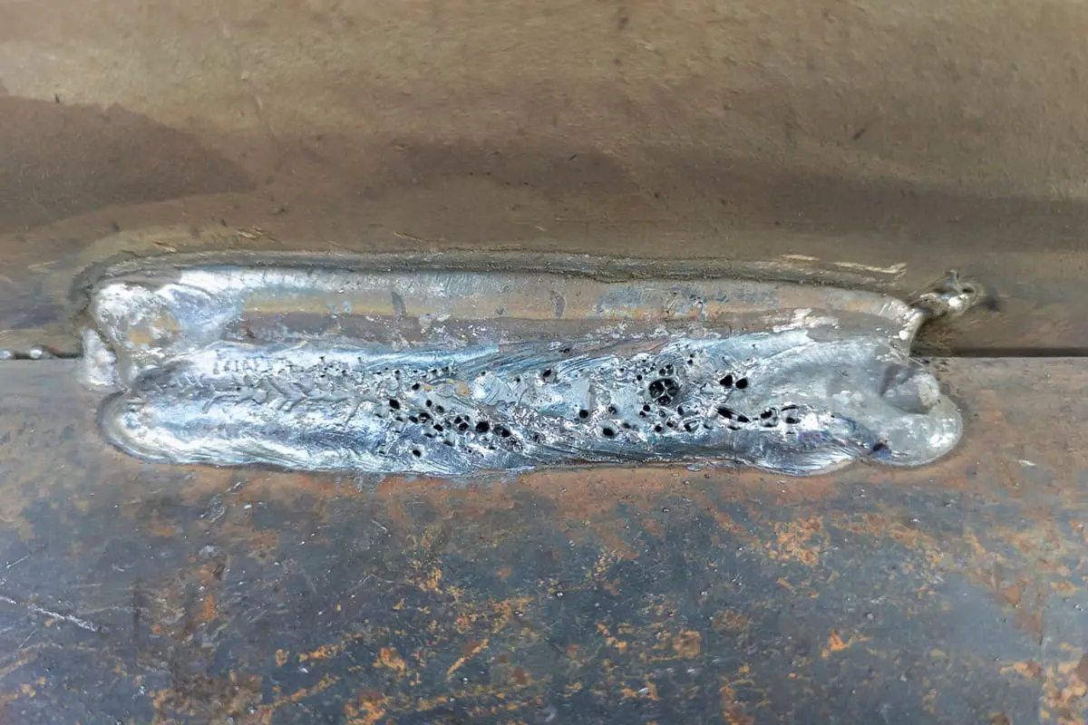
When the expansion rate of the fusion zone is greater than that of the plastic ring under high pressure, the fusion zone breaks through the plastic ring and sprays out, forming welding spatter, which adheres to the surface of the weld and is called welding burrs (Figure 4).
Figure 3: Distribution of welding nucleus
Figure 4: Spatter produced during spot welding
Welding spatter can be divided into two categories: early spatter and late spatter.
1. Early spatter:
During the spot welding heating process, if the heating is too rapid and the surrounding plasticity has not yet formed or is not compact enough, the contact point that is rapidly heated due to the rapid temperature rise will cause internal metal gasification. Under the action of electrode pressure, the liquid metal in the ring will be squeezed out and spray out in the form of spatter towards the gap between the plates.
2. Late spatter:
After the plastic ring is formed during the heating process, heating continues, and the fusion zone and plastic ring continue to expand outward. When the radial expansion rate of the fusion zone is greater than that of the plastic ring, the fusion zone will break through the weakest part of the plastic ring and spray out.
The edge where the electrode cap contacts the sheet metal during the welding process is the narrowest part of the plastic ring. After spraying, sharp welding burrs are often left on the surface of the weld.
3. Spattering caused by the rupture of the liquid bridge
The liquid bridge refers to the thinner part that connects the weld wire or rod to the formed droplet at the end.
Characteristics of Spattering Caused by the Rupture of the Liquid Bridge:
When the liquid bridge ruptures, the spatter is controlled by the bell shape of the welding rod end. Also, the gravity of the droplet and the force of the ionized gas cause the spatter to spread out from the point of rupture of the liquid bridge. The entire spatter range falls from top to bottom in a fan shape formed by the angle of the bell end of the welding rod.
4. Spattering Caused by Temperature Differences
Here, the temperature difference refers to the difference between the arc, the droplet, and the weld pool.
Firstly, the temperature of the welding arc is between 5370 and 7730℃.
Temperature of the Droplet:
The moment the droplet detaches from the welding rod, it becomes a sphere enveloped by a layer of slag. At this point, the gassing agent (CO gas produced from the oxides and carbides in the rod coating) creates a stable, continuous flow of gas, taking away some of the heat from the droplet, resulting in a droplet temperature of around 4000℃.
Temperature of the Weld Pool
Comparison of Three-Phase Temperatures
Generation of Weld Pool Spatter
3. Factors and Measures for Controlling Welding Splatters
1. Operational factors:
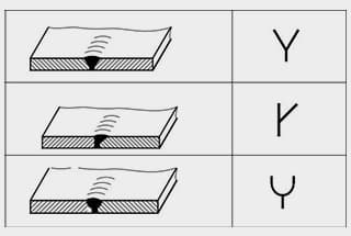
(1) Poor quality of electrode end face: During welding, the electrode cap end face should be kept flat and the size controlled within 6~8mm (Fig.5).
(2) Electrode misalignment: The amount of electrode end face misalignment should be less than 1mm (Fig.6).
(3) Edge welds: The distance between the welding point impression and the edge should be 1mm, allowing for the release of plastic environmental protection.
(4) Oil stains on the sheet metal surface: Before welding, ensure the cleanliness of the sheet metal surface.
Fig.5: Poor quality of electrode end face
Fig.6: Electrode misalignment
2. Welding parameter factors:
Based on the welding principle, it can be seen that the parameters affecting welding include welding current, welding resistance, and welding time. If the welding parameters are too large, the molten metal in the weld pool will expand sharply, causing splatters. This can result in defects such as electrode sticking, electrode explosion, welding breakthrough, etc.
(1) Excessive welding current and welding time:
Set a reasonable welding current and time, and check the output status of the current according to the corresponding frequency.
(2) Excessive welding resistance:
Confirm the surface and fitting status of the sheet metal before welding, and select a reasonable welding pressure to check the output status of the current according to the corresponding frequency.
(3) The welding specification is too hard:
Match the welding current and welding time reasonably, or add a preheating program before the welding procedure so that the sheet metal can form an initial connection and eliminate contact resistance, thereby reducing welding splatters.
Fig.7: Welding Current vs Splatter Relationship Curve
As the welding current increases, the size of the fusion zone or penetration rate also increases. Under normal circumstances, there is a reasonable upper and lower limit for the current in the welding area.
When the current is lower than the lower limit, the heat input is too small to form a standard fusion zone; when the current is higher than the upper limit, the heating speed is too fast, which can cause welding splatters.
To ensure the welding strength and reduce welding splatters, the welding parameters should be selected at the critical point between splattering and non-splattering (Fig.7).
Complex welding cycle diagram:
Fig.8: Complex Welding Cycle Diagram
By adding preheating program and using ramp-up current, the current gradually increases to reduce heating speed (Fig.8).
Through preheating, the plasticity of the sheet metal is improved, making it easier for the panels to fit together, reducing the contact resistance of the panels to a certain extent, and reducing splatters during welding.
On-site validation workstation: XX left/right front longitudinal beam inner panel assembly
Workstation details: X30-2512H: a total of 51 points
Welding tongs status: normal
Before validation: Welding Parameters
Workstation name.
Welding pliers model.
Pre-pressing time.
Pressing time.
Preheating time
Preheating current
Heat cooling
Welding time
Welding current
Ramp-up time
Ramp-up current.
Holding time.
XX
X30-2512H
25
30
0
0
0
25
9.5
0
0
20
Number of splashes: 30-35
Number of burrs: 18-25
Verified: welding parameters.
Workstation name.
Welding pliers model.
Pre-pressing time.
Pressing time.
Preheating time
Preheating current
Heat cooling
Welding time
Welding current
Ramp-up time
Ramp-up current.
Holding time.
XX
X30-2512H
15
30
5
5
2
22
9.0
3
1.0
15
Number of splashes: 6-12
Number of burrs: 2-6
Verified effect diagram:
Tracking effect: Significant improvement in welding splatters and burrs by adjusting welding parameters through process optimization and operation control.
4. Conclusion:
Currently, welding splatter control mainly relies on process optimization and operation control. Due to the welding characteristics and complex on-site environment, it is still not possible to completely eliminate welding splatters.
Therefore, each welder needs to improve their sense of responsibility, observe more, debug more, and improve more, optimize our welding environment, and improve the quality of our body welding, providing higher-quality cars for every car user.
As the founder of MachineMFG, I have dedicated over a decade of my career to the metalworking industry. My extensive experience has allowed me to become an expert in the fields of sheet metal fabrication, machining, mechanical engineering, and machine tools for metals. I am constantly thinking, reading, and writing about these subjects, constantly striving to stay at the forefront of my field. Let my knowledge and expertise be an asset to your business.
Welding symbols may seem like a foreign language, but mastering them is crucial for effective communication in the world of mechanical engineering. In this blog post, a seasoned mechanical engineer…
Ever wondered how skyscrapers stand tall or cars stay welded together? This blog uncovers the magic behind electric welding machines. Learn about top manufacturers like Lincoln Electric and Miller Welds,…
Have you ever wondered how the sleek cars, sturdy bridges, and advanced airplanes of today are built? This article explores six cutting-edge welding technologies that are revolutionizing manufacturing, from laser…
Have you ever wondered why some welded structures fail unexpectedly? This article explores the hidden forces at play—welding stress and deformation. Learn how these stresses impact strength, stability, and accuracy,…
Have you ever wondered how to calculate the consumption of welding rods accurately? In this blog post, we'll explore the methods and formulas used by industry experts to estimate welding…
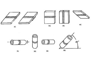
Have you ever wondered about the art of welding and the different positions involved? In this fascinating blog post, we'll delve into the intricacies of welding positions, from flat to…
Ever wondered what "X-weld" or "tack-weld" means? Our latest article breaks down 292 crucial welding terms, offering clear definitions and practical examples. Whether you're a seasoned welder or just starting,…
Why does argon arc welding sometimes produce pores, and how can we fix it? Welding porosity, often caused by impurities, improper gas flow, or incorrect technique, can weaken welds and…
Imagine a machine that welds with precision, never tires, and enhances safety in industrial settings. This article explores the fascinating world of arc welding robots, detailing their components, operational procedures,…