Have you ever wondered why some welds are strong while others fail? This article dives into the critical zones affected during welding: the weld fusion zone and the heat-affected zone (HAZ). Understanding these areas is crucial, as they significantly impact the integrity and performance of welded joints. By exploring the structures and thermal cycles involved, you’ll gain insights into the challenges and methods for improving weld quality. Discover how to optimize welding techniques and materials for stronger, more reliable welds.
During fusion welding, a series of changes from melting to solid-state occur in the weld due to the action of the welding heat source.
Additionally, the structure and properties of the base metal on both sides of the weld that are not melted are changed as a result of the influence of welding heat transfer.
There is also a transition zone between the base metal and the weld that is distinct from both the weld and the base metal and can greatly impact the performance of the welded joint.
1 – Welding seam 2 – Fusion Zone 3 – Heat affected zone 4 – Base metal
1. Structure and performance of fusion zone
The “Fusion Zone” refers to the region where the weld joint transitions into the Heat Affected Zone (HAZ) in a welded joint. This area is very thin and can be difficult to identify even under magnification.
One of the internal defects of steel is known as the “Superheated Structure.” This metal structure is characterized by its large grain size, which is formed when the heating temperature exceeds AC3 for an extended period or when the temperature remains high.
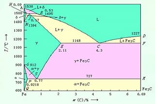
The temperature within the Fusion Zone falls between the solid and liquid phase lines in the iron-carbon alloy’s state diagram. In this area, the metal is in a partially melted state, referred to as the “Semi-Molten Zone,” and has very large grains. After cooling, the resulting structure is a coarse, overheated structure with poor plasticity and toughness.
Due to the obvious chemical and structural heterogeneities within the Fusion Zone, it is often the source of cracks or local brittle failures in welded joints and represents the area with the lowest neutral energy of the welded joint.
2. Welding thermal cycle
The process by which the temperature of a point on a weldment changes over time under the influence of the welding heat source is known as the “Welding Thermal Cycle.” This term refers to a specific point on the weldment where the heat source is close.
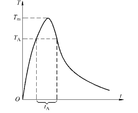
During the Welding Thermal Cycle, the temperature at the point increases until it reaches its maximum value. As the heat source moves away, the temperature gradually decreases back to room temperature. This process can be represented by a curve.
Welding thermal cycle curve
Tm – maximum temperature of heating
TA – phase transition temperature
tA – residence time above phase transition temperature
3. Structure and properties of welding heat affected zone
The “Welding Heat Affected Zone” (HAZ) refers to the region where the metallurgical structure and mechanical properties of the base metal are altered as a result of heat exposure (but not melting) during the welding process. The characteristics and properties of the HAZ are a reflection of the properties and quality of the welded joint.
For low-carbon steel and low-alloy high-strength steel with minimal alloying elements, the Welding Heat Affected Zone can be divided into the “Overheated Zone,” the “Normalizing Zone,” the “Incomplete Recrystallization Zone,” and the “Recrystallization Zone.”
Welding heat affected zone of non quenchable steel
Fusion Zone
Overheated Area
Normalizing Area
Incomplete Recrystallization Zone
Recrystallization Zone
Base Metal
Overheated structure: widmanstatten structure
In the superheated zone of the Welding Heat Affected Zone, the formation of a coarse austenite grain results in a special overheated structure under fast cooling. This structure is characterized by parallel ferrite (cementite) needles within the coarse austenite grain, with the remaining austenite between the needles being transformed into pearlite. This overheated structure is known as the “Ferrite (Cementite) Widmanstatten Structure.”
In simple terms, when the austenite grain is coarse and the cooling rate is suitable, the pre-eutectoid phase in the steel forms a needle-like flake pearlite. The Widmanstatten Structure not only has a large grain size, but also has a significant decrease in metal flexibility due to the fragile surface created by numerous ferrite needles, which is a major cause of the embrittlement of the welded joint in steel that is not easily quenched.
The width of the Heat Affected Zone (HAZ) is influenced by several factors, including the welding method, welding parameters, size and thickness of the weldment, thermal physical properties of the metal material, and joint form.
It is possible to reduce the width of the HAZ by using smaller welding parameters, such as reducing the welding current and increasing the welding speed.
The width of the HAZ varies depending on the welding method used. The total width of the HAZ for electrode arc welding is approximately 6mm, while it is around 2.5mm for submerged arc welding and approximately 27mm for gas welding.
Methods for controlling and improving the properties of welded joints
1. Material matching
Material matching” primarily relates to the choice of welding materials.
For low-carbon steel, low-alloy high-strength structural steel, and low-temperature steel, the composition of the weld metal and base metal does not need to be identical, however the mechanical properties must be the same as the base metal.
When working with heat-resistant steel and stainless steel, to ensure that the weld has similar high temperature performance and corrosion resistance as the base metal, the chemical composition of the welding material should closely match that of the base metal.
2. Control the fusion ratio
In fusion welding, the proportion of melted base metal in the weld metal is referred to as the fusion ratio.
The calculation formula of fusion ratio is:
r = Fm/(Fm+Ft)
Where
r – fusion ratio;
Fm – cross sectional area of molten base metal:
Ft – cross sectional area of filler metal in the weld.
As the founder of MachineMFG, I have dedicated over a decade of my career to the metalworking industry. My extensive experience has allowed me to become an expert in the fields of sheet metal fabrication, machining, mechanical engineering, and machine tools for metals. I am constantly thinking, reading, and writing about these subjects, constantly striving to stay at the forefront of my field. Let my knowledge and expertise be an asset to your business.
Welding fumes pose a significant hazard to both the environment and worker health, containing toxic gases and fine particles that can lead to serious respiratory and systemic illnesses. This article…
Imagine building a bridge or a skyscraper, only to have it fail due to unnoticed flaws in the welding. Fatigue strength in welded structures is a critical factor in ensuring…
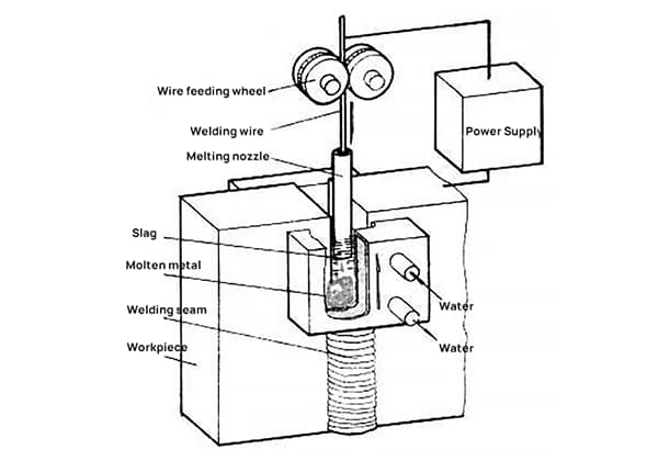
Have you ever wondered how to weld extremely thick metal pieces without multiple passes? Electroslag welding (ESW) offers an efficient solution, using molten slag to generate the necessary heat for…
Ever wondered how skyscrapers stand tall or cars stay welded together? This blog uncovers the magic behind electric welding machines. Learn about top manufacturers like Lincoln Electric and Miller Welds,…
Have you ever wondered how to calculate the consumption of welding rods accurately? In this blog post, we'll explore the methods and formulas used by industry experts to estimate welding…
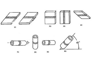
Have you ever wondered about the art of welding and the different positions involved? In this fascinating blog post, we'll delve into the intricacies of welding positions, from flat to…
Ever wondered what "X-weld" or "tack-weld" means? Our latest article breaks down 292 crucial welding terms, offering clear definitions and practical examples. Whether you're a seasoned welder or just starting,…
Imagine a machine that welds with precision, never tires, and enhances safety in industrial settings. This article explores the fascinating world of arc welding robots, detailing their components, operational procedures,…
Choosing the right welding robot can transform your manufacturing process, but where do you start? This guide dives into crucial factors like degrees of freedom, load capacity, and working space.…