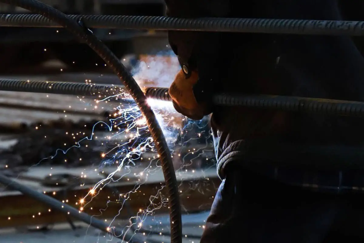
Spot Welding: Tips and Techniques for Precision Bonding
Imagine a world where metals fuse seamlessly with just a spark. This is the essence of spot welding, a technique that binds metal parts with precision and strength. In this…
Spot welding is a crucial technique in manufacturing, but how much do you really know about it? In this blog post, we dive deep into the intricacies of spot welding, exploring its working principles, key stages, and critical factors that influence weld quality. Whether you’re an engineer or simply curious, join us on this fascinating journey to unravel the secrets behind this essential joining method.
The working principle of spot welding is based on the thermal effect of current. In spot welding, two workpieces to be welded are first clamped by the upper and lower electrodes under the action of a welding clamp or welding gun cylinder.
Then, a welding current (usually ranging from a few thousand to tens of thousands of amperes) melts the metal at the welding point according to Joule’s Law, Q=0.24I²Rt. Once the welding temperature is reached, the current is cut off. Under the pressure of the electrode, the molten metal cools and crystallizes to form a weld nugget.
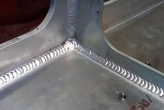
Spot welding is mostly used for thin plate welding, and the joint styles often adopt lap joints and flanged joints.
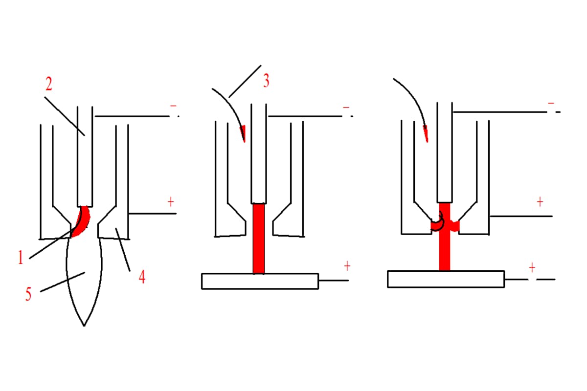
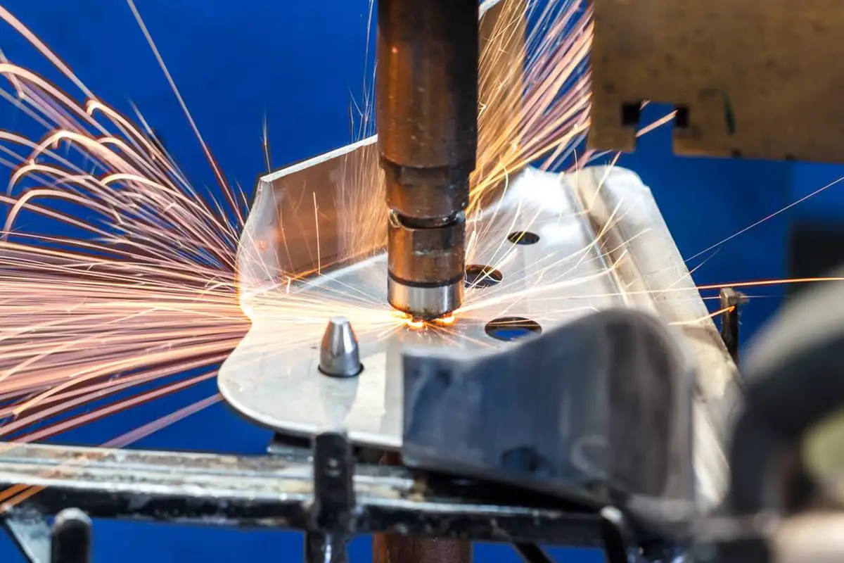
There are many types of spot welding. We primarily use two types in our assembly workshop: double-sided single-point and single-sided double-point.
Double-sided single-point
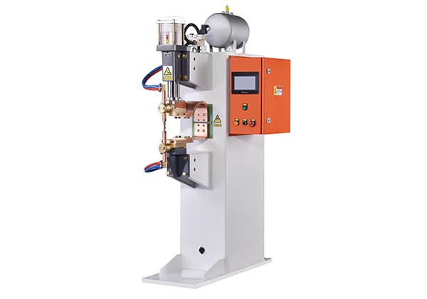
The double-sided single-point is the most widely used form of spot welding. Examples include hanging spot welding machines and seat spot welders. Its characteristic is that only one spot can be welded at a time.
Single-sided double-point
The single-sided double-point is mainly applied on the same surface of the workpiece, with a large piece of copper conductive plate (block) with excellent conductivity on the other side.
The two ends of the secondary wire of the welding transformer are connected to the electrodes, and the workpiece is pressed between the electrode and the copper pad.
Therefore, insulating materials must be used to separate the electrode block from the electric block support when assembling multiple spot welding machine electrode blocks. During maintenance, the original insulating pad must be installed to prevent shunting when welding.


Each spot welding process must go through four stages: squeeze, welding, hold, and rest. Each stage lasts for a certain period of time, specifically squeeze time tsqueeze, welding time tweld, hold time thold, and rest time trest. These four processes are indispensable for the quality of spot welding. As shown in the diagram:
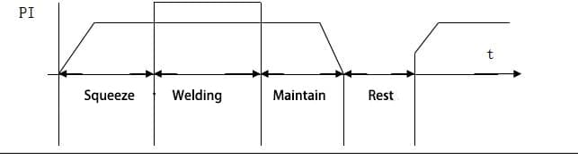
(1) Squeeze:
Squeeze time refers to the time from when the electrode starts to apply pressure to the workpiece to the start of electrification. During this time, the electrode must apply the necessary pressure for welding to ensure close contact between the workpieces.
If the squeeze time is too short and electrification starts before the two workpieces are in close contact, the high contact resistance may result in burn-through during spot welding.
(2) Welding:
Welding time refers to the duration of electrode contact during the spot welding process, a crucial step in the process. During welding, the current passing through the electrode flows into the workpiece, generating intense resistive heat at the welding point.
The metal at the heat’s focal point melts first, and the molten metal is surrounded by the yet unmelted metal and plastic state metal ring, preventing the molten metal from spilling out.
As time progresses, the molten nucleus expands. The heating speed during welding is very fast, and the core temperature of low carbon steel spot welding can reach over 1800°C (exceeding the metal’s melting point by 200-300 degrees) within 0.06 to 0.1 seconds. Sometimes, when the current is too high or the welding time too long, spatter may occur under the pressure of the electrode.
In general, a small amount of spatter is acceptable, but excessive spatter can affect the welding quality and create deep dents. Typically, the dent depth should not exceed 20% of the part’s thickness.
(3) Maintenance:
The maintenance time refers to the period from power off to electrode lifting, during which liquid metal within the plastic ring crystallizes under pressure, forming the welding nucleus.
If the welding current is cut off before the liquid metal in the welding nucleus has time to crystallize and the electrode lifts, the welding nucleus metal will solidify in the enclosed plastic ring, resulting in shrinkage or porous structures due to insufficient volume replenishment.
Clearly, the strength of a welding nucleus with shrinkage or porous structures is very low, so the maintenance time is indispensable.
This ensures that the welding nucleus crystallizes under pressure, resulting in a dense structure. For low-carbon steel sheets with a thickness of 1-1.5 mm, the maintenance time is 0.1-0.2 seconds, while for welding low-carbon steel with a thickness of 8-10 mm, the full crystallization of the welding nucleus requires around 1.5-2.5 seconds.
Therefore, the maintenance time should not be less than this value. However, excessively long maintenance times are not desirable either.
(4) Rest:
Rest time refers to the period from the electrode lifting from the workpiece to the start of pressure application in the next cycle. As long as it satisfies the time requirements for workpiece movement, positioning, and the mechanical actions of the welding machine, the shorter this time, the better, as it results in higher productivity.
The above-mentioned spot welding cycle is the most basic one and is indispensable for spot welding of any metal or alloy.
The heat source of spot welding is the resistance heat generated when current passes through the metal being welded.
Therefore, the resistance during spot welding and its distribution are critical factors affecting the quality of spot welding. The resistance R during spot welding includes the contact resistance R pole between the electrode and the workpiece, the effective resistance R piece of the workpiece, and the contact resistance R touch between workpieces.
The relationship is: R = 2Rpole + Rtouch + 2Rpiece, then the resistance heat generated during spot welding is: Q = 0.24I2(2Rpole + 2Rtouch + 2Rpiece)t.
It is noteworthy that during the spot welding process, as the workpiece is heated and the temperature gradually rises, both the inherent resistance of the workpiece and the contact resistance, as well as the welding current, exhibit significant changes.
Hence, accurately calculating the resistance heat produced during spot welding using Joule’s first law is challenging. Below are three key resistances related to spot welding.
The contact resistance is related to the electrode pressure, the properties of the material, and the surface condition of the parts. As the electrode pressure increases, the protrusions on the surface of the welding workpiece are crushed, increasing the number and area of contact points, thereby reducing the contact resistance.
In spot welding, when the welding machine capacity is small, sometimes the contact resistance is adjusted by changing the electrode pressure to regulate the heat during spot welding and improve welding quality.
Similarly, if the material is softer, the crushing strength is lower. Therefore, under the same pressure, the contact surface increases, reducing the contact resistance. When oxides and dirt, especially low-conductivity oxides, are present on the welding surface, they significantly inhibit the passage of current and increase contact resistance.
Contact resistance also depends on temperature. During the welding heating process, as the temperature of the workpiece gradually rises, the crushing strength of the contact points decreases, rapidly increasing the contact area and drastically reducing contact resistance. When the temperature of the steel part is close to 600°C, its contact resistance virtually disappears.
The contact resistance between the electrode and the workpiece is generally about half of the contact resistance between workpieces, i.e., Rpole = 0.5Rtouch. This resistance is harmful to spot welding; the smaller it is, the better.
If this resistance is too high, the temperature at the contact point between the electrode and the workpiece becomes excessive, causing surface spatter or burn-through. Moreover, the electrode can easily weld with the workpiece, severely wear out the electrode, and create difficulties in spot welding.
Oil stains, impurities, and rust on the workpiece surface can all lead to these adverse effects. Additionally, when the electrode carries iron materials, it must be cleaned thoroughly before welding.
During spot welding, the heat required to form the welding nucleus is mostly generated by the internal resistance of the workpiece, accounting for over 90% of the heat needed for the welding nucleus.
The effective internal resistance R piece of the workpiece is related to the thickness of the part, the diameter D of the contact surface between the electrode and the workpiece, and the resistance coefficient of the welded workpiece material, which can be represented by the following equation:
Rpiece = Kxδ⁄D²ΧP
where:

During spot welding, the total heat Q produced by the current passing through the workpiece resistance and contact resistance can be divided into two main parts. One part of Q is consumed at the welding location and its adjacent areas, heating this part of the metal to the welding temperature to enable welding.
This part of the heat is useful for achieving welding, and we call it effective heat Q effect. The other part of the heat is used to compensate for the heat Q1 of the cold metal around the welding location, the heat Q2 taken away by the electrode and the cooling water, and the heat Q3 radiated to the surrounding air.
This part of the heat is not used to heat the metal being welded and is useless for the thermal formation of the welding nucleus. It is a waste of heat and is therefore called useless heat or lost heat. As shown in the figure:

The relationship above can be expressed using a balance equation:
Q = Qeffective + Qloss = Q1 + Q2 + Q3 + Qeffective
The size of the effective heat depends on the volume, temperature, and thermal physical properties of the welding area or metal. When the volume of the metal material in the welding area is fixed, it has no relationship with the heating time. However, the heat loss Qloss is related to the length of heating time, the longer the time, the greater Qloss.
Qeffective is closely related to the volume, temperature, and thermal physical properties of the metal in the welding area. The thicker the workpiece, the larger the volume of the metal in the welding area, hence, the more heat is needed during spot welding.
Qloss is also related to the volume of the metal, the thermal physical properties of the metal material, and the temperature of the surrounding medium.
When the size of the welding workpiece is larger, the thermal conductivity of the metal is better, the temperature of the surrounding medium is lower, and the welding time is longer, then Qloss is also more. This means that some colored metals with good thermal conductivity are more difficult to spot weld than low carbon steel.
Additionally, Qloss increases with time, so during welding, under the premise that the power of the welding machine is sufficient to ensure welding quality, try to use shorter welding times and larger welding currents.
The relationship between the heating temperature of the welding area and the heating time is that no matter how powerful the welding machine is, as the heating time increases, the temperature at the beginning of the welding area rises rapidly and finally tends to a constant value.
This is because as the heating time extends, although the heat released by the electrode is increasing, the heat conducted to the surrounding cold metal, the electrode, and the heat lost to the surrounding medium is also increasing.
Finally, the heat released by the resistance per unit time and the heat loss are equal, reaching a balanced state, so the working temperature also reaches a stable value.
Therefore, to obtain high-quality weld spots, you can’t endlessly use the method of extending the welding time to reduce the thermal efficiency to achieve the welding time, the temperature of the area to be welded on the workpiece will never reach the welding temperature.
The spot welding specification involves the range of parameters closely related to welding quality to ensure good welding quality during the spot welding process. The main process parameter specifications during spot welding include welding current, welding time, electrode pressure, and electrode working face diameter.
The specification of spot welding parameters has a very important relationship with the quality of spot welding. Therefore, it is necessary to carefully analyze the relationship between the specification of spot welding parameters and the quality of spot welding.
During spot welding, the heat generated by the resistance in the welding area is:
Q=0.24I_weld²•R•tweld (cal)
Where:
During spot welding, if the electrode pressure Ppole, the diameter of the contact surface between the electrode and the workpiece, the material of the workpiece, thickness, and surface quality remain unchanged, then the resistance R is basically unchanged. The heat generated by the resistance from the equation above is related to the current Iweld and time tweld. As the welding current and welding time increase, more and more heat is generated at the welding site, especially the effect of the current is greater.
During spot welding, the size of the welding nucleus formed is related to the heat released by the resistance, thus Iweld and tweld directly affect the strength of the spot during spot welding. The curve shown in the graph represents the thickness


When low carbon steel sheets in millimeters are spot-welded, there is a relationship between the tensile strength of the weld spot (PB) and the welding time (t). As illustrated in the figure, the weld spot strength (PB) initially increases rapidly with the welding time, then slows down, and finally decreases if the welding time is too long.
Figure 2 shows the cross-sectional view of the weld nugget quality at points A, B, C, D in Figure 1. When the welding time is very short, equivalent to point A in Figure 1, the heat released by the resistance is too little to melt the core metal.
Therefore, only a small portion of the metal in the welding area is plastically welded under the influence of the electrodes, and a weld nugget cannot be formed, as shown in Figure 2a.
If the welding time increases, between points A and B in Figure 1, the temperature of the welding area gradually rises, but has not yet reached the temperature required for welding, as shown in Figure 2b.
The weld nugget is small and not strong at point B in Figure 1. From Figure 1, we can see that the slope of the line segment A-B is relatively large, meaning any slight changes in the welding time and other factors result in significant fluctuations in welding quality, leading to large variations in quality.
When the welding time (t) is extended, as shown in the B-C segment in Figure 1, the heat released by the resistance gradually raises the temperature at the welding point to the temperature required for spot welding, as shown at point C in Figure 2 for Figure 1.
The weld nugget has reached the required geometric size and the welding quality is at its best. At the same time, the curve at point C is the flattest, minor changes in welding time and other factors lead to smaller variations in welding quality, resulting in the most stable strength.
Therefore, point C in Figure 1 is generally chosen as the standard for spot welding.
During the spot welding process, the normal weld nugget diameter is approximately 0.9 to 1.4 times the diameter of the contact surface between the electrode and the workpiece. That is:
dnugget = (0.9~1.4) delectrode
If the welding time is further extended, as shown in the C-D segment in Figure 1, the welding quality begins to gradually decline. This is because the heating time is too long on the one hand, causing severe overheating in the areas near the weld nugget due to the widened heating area.
On the other hand, because the welding time is too long, the melted core becomes too large, and the plastic metal ring outside the core cannot contain the melted metal under the pressure, leading to excessive spattering, deep indentation, reducing the effective cross-sectional area of the weld spot, and decreasing the weld spot strength, as shown in Figure 2d.
Since the relationship between the welding current and the quality of the weld spot is similar to the relationship between the welding time and the quality of the weld spot, it is not restated here.
The electrode diameter refers to the diameter of the contact surface between the electrode and the workpiece. The electrode diameter has a close relationship with the welding quality. If other process parameters are kept constant, the welding area current density decreases and heat dissipation intensifies as the electrode diameter increases.
This enlarges the contact surface between the electrode and the workpiece, both of which are unfavorable for the formation of the weld spot and lead to a decrease in welding strength.
During the spot welding process, the electrodes inevitably wear or pile up as the number of weld spots increases. As the diameter of the contact surface between the electrode and the workpiece gradually enlarges, the strength of the weld spot decreases. Therefore, continuous maintenance of the electrodes is required during the welding process.
Under normal circumstances, the diameter of the contact surface between the electrode (d) and the workpiece (thin plate) thickness (δ) has the following relationship:
During spot welding, electrode pressure is one of the most important parameters in the spot welding process specifications. The size of the electrode pressure (P) directly affects the heating state of the welding metal area.
When the pressure (P) is too low, the workpiece surface has poor contact, resulting in high contact resistance, which can burn through the workpiece and sometimes damage the electrode.
If the pressure (P) is too low, the pressure applied by the electrode on the workpiece may be less than the rigidity force overcoming part deformation, making it impossible for the two workpieces to come into contact at the welding point, and the weld nugget cannot form at the welded place.
The force applied by the electrode on the workpiece can be divided into two parts: one part overcomes the elastic deformation of the part to enable the workpiece to contact, and the other part is used to press the welding contact surfaces against each other.
The force overcoming the deformation of the workpiece and the pressure applied by the electrode on the workpiece are related to the thickness of the workpiece, and the pressure increases as the thickness of the workpiece increases.
Under the condition of unchanged other parameters, as the electrode pressure increases, the strength of the weld spot gradually decreases.
Because as the electrode pressure increases, the current density decreases, and the amount of heat lost increases, the heating of the welding area becomes more difficult, inevitably reducing the size of the weld nugget and decreasing the welding quality.
If the welding current is increased while increasing the electrode pressure, or if the welding time is appropriately extended while increasing the electrode pressure to maintain the strength of the weld spot, the strength of the weld spot becomes more and more stable as the electrode pressure increases.

Shunting during spot welding refers to a portion of the current bypassing the welding area of the workpiece and forming another circuit. The current flowing through the non-welded area is called shunt current.
When a weld spot is being welded, a part of the current bypasses the welding area and forms another circuit because the workpiece and the welding arm are in contact. Shunting reduces the current flowing through the welding area, resulting in insufficient heating of the weld spot and quality issues such as poor welding.
At the same time, in the shunt circuit, the contact area between the workpiece and the clamp arm is prone to “fire”, burning the welding clamp and the workpiece.
There are various reasons for shunting, and in some cases, shunting has a significant impact on the quality of the weld spot. Therefore, shunting that should occur in spot welding should be eliminated in time.
Here are some common shunting phenomena during spot welding:
The secondary wire of the welding machine transformer and the machine body are both insulated. If maintenance is not carried out in time, poor insulation or breakdown will cause shunting, and in serious cases, welding cannot be carried out.
For example, the conductive clamp part of a multi-point welding machine, insulated joints, gaskets, etc. should be regularly tested for insulation performance, and problems should be repaired in time. Generally, the insulation resistance should not be less than 0.5 megaohm per kilovolt.
The smaller the distance between two adjacent weld spots, the smaller the resistance of the shunt path, and the greater the shunting.
Therefore, during spot welding, the spot distance should be selected according to the process requirements to reduce the influence of shunting.
As the thickness of the workpiece increases, shunting becomes more severe. This is because the increase in workpiece thickness increases the metal conductive cross-sectional area of the shunt path, reduces the resistance of the shunt path, and therefore increases the shunting.
During the spot welding process, when spot welding two layers of plates at a time, the shunting from the adjacent weld spot is smaller than when spot welding three layers of plates at a time, because the increase in the number of workpieces is equivalent to the increase in the thickness of the workpiece.
Furthermore, the welding sequence of the weld spot, the surface condition of the workpiece, and the electrode pressure all have an effect on shunting during spot welding.
In short, there are many factors causing shunting, and their impacts on spot welding are different. Among them, the shunting caused by the contact of the secondary circuit has a greater impact on the quality of spot welding and should be regularly checked to avoid the occurrence of shunting.
Quality weld spots, both externally and internally, should have no defects. Externally, weld spots should be round and smooth, free of burns, deep indentations, and various other defects.
Internally, there should be an appropriately sized, densely cast weld nugget that does not contain defects such as shrinkage holes, looseness, or cracks.
Defects can occur in spot welding if the workpieces are not properly cleaned or if the selection of standards is inappropriate.
The main defects in spot welding include:
Lack of fusion occurs when a “lentil” shaped cast spot weld structure is not formed during spot welding. This defect is the most dangerous because it significantly reduces the strength of the weld spot. Moreover, this defect generally cannot be detected from the outside.
The main causes of lack of fusion are insufficient heating of the welding area due to too low welding current density or short welding time. There are various reasons why the current in the welding area is reduced, such as inappropriate adjustment of welding process specifications, increased resistance in the secondary circuit, the presence of shunting, or a drop in network voltage.
Spatter often occurs in spot welding. A little bit of spatter is inevitable, but if the spatter is too large, it will cause deep indentations. If the depression on the working surface is too deep, the strength of the weld nugget will be significantly reduced. There are two types of spatter, initial spatter and final spatter.
Initial spatter occurs at the moment the current is closed. The main reasons are too short pre-pressure time, unclean workpiece surface, or low pressure. End spatter occurs at the end of electrification.
The main reasons are too large welding current or too long welding time, leading to a large amount of melted metal in the core that cannot be contained by the surrounding plastic ring under electrode pressure, resulting in the overflow of liquid metal.
The way to eliminate spatter is to find the cause of the spatter and properly adjust the welding specifications or improve the surface quality of the workpiece.
The main reasons for this defect are unclean workpiece surface, non-flat or metal-adhering electrode surface, and improper adjustment of welding specifications.
The depth of the electrode indentation on the surface of a normal weld spot should not exceed 20% of a workpiece thickness. The main reasons for overly deep electrode indentation are severe overheating of the weld spot, severe spatter, too small electrode surface diameter, and too large workpiece assembly gap.
The main reason for cracks is too fast cooling, which is a common defect in welding alloy steel and is rarely seen in welding low carbon steel.
Looseness and shrinkage holes are mainly caused by too low electrode pressure or too short holding time.
Among the above defects, lack of fusion, melting of the workpiece surface, burn-through, and serious spatter resulting in too deep indentation are common in spot welding of low carbon steel.
The electrodes used in spot welding are used to transfer pressure and current to the workpiece. With the current spot welding machines that can weld more than 60 spots per minute, electrode wear during spot welding is significant.
If the electrode material is poor or the electrode structure design is unreasonable, the electrode wear will be exacerbated during use, which increases the time for electrode repair and wastes a lot of electrode material.
Therefore, the selection of electrode materials and electrodes should be determined based on their use. The electrode material for spot welding of low carbon steel should meet the following points:
Good electrical and thermal conductivity. The chromium-zirconium-copper electrode we use cannot be less than 75% of pure copper. Because if the electrical and thermal conductivity is not good, not only will the temperature of the electrode rise and the strength decrease, the electrode wear will also be aggravated. Moreover, severe adhesion can occur, causing some workpiece metal to stick to the electrode and cause burn-through.
It has a certain high-temperature hardness, especially at 500-600°C, it can still maintain this hardness. The higher the high-temperature hardness, the less likely the electrode is to pile up during the welding process.
Generally, the temperature at the contact point between the workpiece and the electrode during spot welding is about half of the melting point of the welded metal. If the electrode material has a high hardness at room temperature but a low hardness at high temperatures, it is still prone to piling up during the spot welding process.
It has a certain high-temperature oxidation resistance to reduce the tendency of the contact surface of the electrode and the workpiece to oxidize during spot welding. This reduces the contact resistance to ensure the stability of the welding quality.
The above three conditions are contradictory. Pure copper has the best electrical and thermal conductivity compared to chromium-zirconium copper, but it has low hardness, especially at low recrystallization temperatures. Therefore, copper cannot be used as an electrode.
The influence of electrode shape and size on electrode performance is as follows:
1. The diameter of the electrode contact surface, d, is generally determined by the thickness of the workpiece.
And the electrode cone angle can be selected according to the structure of the workpiece. From the perspective of electrode service life, the larger the cone angle, the better the heat dissipation, the less likely the electrode is to pile up, and the less likely it is to deform. Generally, around 1050 is appropriate.
The distance from the bottom of the electrode cooling water hole to the end face of the electrode has a great relationship with the performance of the electrode.
Because the smaller this distance, the better the electrode is cooled, the more welding spots per unit length of wear, and the less the electrode bonding phenomenon. But if this distance is too small, overall, the life of the electrode decreases.
If the distance is too long, when the electrode starts to use, the number of welding points welded per unit length of electrode wear is small, and the tendency to stick to the electrode is greater.
Generally, the distance from the bottom of the electrode cooling water hole to the end face of the electrode is 10-15mm. When the electrode is worn to 2-3mm, although the number of welding spots welded per unit length of electrode wear is large, hardening can occur easily for metal materials with a high tendency to quench.
2. The distance from the end of the water core to the bottom of the electrode cooling water hole.
The distance from the end of the water core to the electrode cooling water hole has a great relationship with the service life of the electrode. If the distance is too short, the cooling water will not flow smoothly, and the electrode will not cool well.
During use, the electrode is prone to heat, pile up, increase wear, serious electrode sticking, which will reduce the life of the electrode and it is difficult to guarantee the quality of welding. But if it’s too long, because the water at the bottom doesn’t move, “dead water” will appear at the bottom of the electrode cooling water hole.
Therefore, this part of the water will vaporize and block the cooling water due to the continuous rise in temperature during welding. This makes the electrode cooling poor, affects the quality of welding, and the life of the electrode decreases. Generally, the distance from the water core to the bottom of the electrode is 6-8mm.
3. The shape of the working surface of the spot welding electrode is determined according to the shape of the workpiece and the properties of the material.
The shape of the commonly used electrode working surface can be selected according to the specific situation. All kinds of electrodes we use are specified in the process card and cannot be easily changed.
Low carbon steel possesses excellent weldability. The process parameters of low carbon steel can vary within a wide range, resulting in good spot welding strength, regardless of whether the specifications are stringent or not.
The discussion is broken down as follows:
Before welding, the surface of the workpiece should be carefully cleaned to reduce the impact of contact resistance on the quality of spot welding. When spot welding cold rolled steel plates, due to the absence of an oxide layer, no special treatment is generally required.
However, if there is drawing oil or surface uncleanliness during the drawing process and high surface quality is required for the parts, pre-welding cleaning should be conducted. If the surface is rusty or dirty, it should also be cleaned thoroughly to prevent quality issues such as burn-through or poor welding due to poor contact.
The welding quality is not only related to the welding method and specification parameters used, but also significantly linked to the machining accuracy and assembly precision of the parts. If the accuracy of the parts is low or unstable, it can result in excessive assembly gaps and burn-through during welding.
When spot welding thin plate structural parts, the assembly gap should not exceed 0.5 to 1.0 mm. When spot welding thick plate hook parts or parts with high stiffness, the assembly gap should be even smaller, preferably not exceeding 0.1 to 0.2 mm.
If the part gap is too large, effective measures should be taken; welding should only commence once the workpieces are in good contact to prevent burn-through or poor welding.
The shape of the electrode is determined according to the workpiece and structure as per process requirements, and the specifications of the electrode and electrode rod should not be easily altered.
During the welding process, it’s essential to ensure that the centerlines of the electrodes coincide, and the shape of the electrode head meets the structural requirements of the workpiece.
Moreover, the electrode gap should not be too large or too small. If any non-compliance is found, timely replacement and adjustment should be made to avoid quality defects such as excessive spatter, burn-through, and offset of the weld nugget.
During the spot welding process, the electrodes often wear, causing the diameter of the electrode contact surface with the workpiece to gradually increase. The increase in diameter should not exceed 20% of the process specification weld nugget diameter, and if it does, timely repair is required.
If the workpiece surface is unclean, or the electrode pressure is too low, or the assembly is poor, causing the workpiece to burn through, the electrode contact surface will often melt many iron metals.
If not filed away, continued spot welding will cause further burn-through. Therefore, once it is found that the electrode surface is adhered with iron metal, it must be filed or repaired with a special tool before welding.
Regardless of whether strong or weak specifications are used, good spot welding quality can be achieved with low carbon steel.
Using strong specifications can significantly increase productivity, reduce power consumption, and minimize weld nugget deformation. Strong specification welding requires higher welding machine power, so it is often used in large-scale production. Weak specifications can be used for spot welding on welding machines with lower power.
However, due to the longer welding time with weak specifications, not only is the production rate low, but power consumption is higher, and welding deformation is also greater. Therefore, as long as the power of the welding machine is sufficient, larger specification welding should be adopted as much as possible.
The following are the specification parameters for spot welding low carbon steel components with a thickness of 0.5mm to 2.0mm using strong specifications, which can be selected based on specific circumstances.
| Sheet Thickness (mm) | Electrode Diameter (mm) | Electrode Pressure (kg) | Welding Duration (s) | Welding Current (A) | Power (Kilovolt-amps) |
| 0.5 | 4 | 70~120 | 0.10.2 | 4000~5000 | 10~20 |
| 1.0 | 5 | 100~200 | 0.20.4 | 6000~8000 | 20~50 |
| 1.5 | 6 | 150350 | 0.250.5 | 8000~12000 | 40~60 |
| 2.0 | 8 | 250~500 | 0.350.6 | 9000~14000 | 50~75 |
When the thickness difference between workpieces is within three times, spot welding is not difficult. At this time, the welding specification parameters are mainly determined by the workpiece, and the welding current can be increased or the welding time can be extended appropriately.
When the thickness difference between two pieces is too large, if no special measures are taken, the nugget will form near the center of the thickness sum of the two workpieces, and the workpieces cannot be welded together.
If the electrode diameter in contact with the thin plate is reduced and the electrode diameter in contact with the thick plate is increased, the thick plate has better heat dissipation than the thin plate, so the nugget shifts towards the thin plate side, making it precisely at the contact part between the two plates, thus welding the pieces together.
When spot welding three-layer plates, the specification parameters can be determined according to the following principles:
① When two thin plates are on both sides of a thick piece, the specification can be determined by the thin plate, while appropriately increasing the welding current or extending the welding time.
② When a thin plate is between two thick pieces, the specification can be chosen according to the thick piece, while reducing some welding current.
Spot welding of low carbon steel plate with a thickness greater than 5mm (referring to a single piece) is relatively difficult. The reasons are:
① The thicker the workpiece, the greater the rigidity, thus the greater the electrode pressure required.
② Thick steel plates are generally hot-rolled, with a thick black oxide skin on the surface which is difficult to clean.
③ Due to the high electrode pressure and long welding time, the electrode wear and consumption are considerable.
④ Large shunting.
⑤ Large welding machine power is needed. The most prominent issues are the high power of the welding machine and the large electrode consumption. Generally, for spot welding of low carbon steel plates with a thickness greater than 5mm, a power of more than 200KVA is required, and the supplied electrode pressure and current are very large.
If ordinary spot welding cycle (once electrified) is used for spot welding thick steel plates, the electrode will wear out quickly under high temperature and pressure due to the long electrification time, making welding difficult.
To reduce electrode wear, we can adopt a pulse spot welding cycle, that is, not using continuous electrification during welding, but a multiple pulse spot welding cycle of electrification — power off — electrification — power off.
This allows the electrode to cool down during the power gap time, greatly reducing electrode consumption. The number of pulse electrifications, the length of electrification time, and gap time depend on the thickness of the workpiece.
Projection welding is a variant of spot welding, and its welding specifications are roughly the same as spot welding. Projection welding is often used for thin plate welding.
The process feature of projection welding is to achieve welding at the contact point of the workpiece with one or several convex points of a certain geometric size punched on one of the pieces to be welded.
The convex points play a role in mediating pressure and current, thus projection welding saves electricity and has a higher production rate. However, projection welding has higher requirements for the geometric size of the convex points, and the control of pressure and electrification.

As the founder of MachineMFG, I have dedicated over a decade of my career to the metalworking industry. My extensive experience has allowed me to become an expert in the fields of sheet metal fabrication, machining, mechanical engineering, and machine tools for metals. I am constantly thinking, reading, and writing about these subjects, constantly striving to stay at the forefront of my field. Let my knowledge and expertise be an asset to your business.