Although there are no technical secrets in the welding process, there are various welding technologies, methods, and processes that can make the welding process easier. These processes are referred to as technical know-how.
Welding know-how can save time, cost, and labor and can even determine the success or failure of welding, as well as profit and loss. Most welding processes are based on scientific research, while some rely on actual welding experience.
This article aims to introduce the practical synthesis of welding experience.
1. Welding process problems and Solutions
1.1 Welding of thick plate and thin plate
1.1.1 When welding steel workpieces with GMAW and FCAW, if the thickness of the workpiece exceeds the maximum welding current of the welder, how to deal with it?
To prevent weld cracking or incomplete fusion, the metal should be preheated before welding. The welding area of the workpiece can be preheated using propane, standard gas, or acetylene torch. The recommended preheat temperature range is 150-260 ℃, after which the welding process can be initiated. The primary objective of preheating the metal in the welding area is to avoid rapid cooling, which may cause issues with the weld area.
1.1.2 If it is necessary to weld a thin metal cover on a thick steel pipe by GMAW or FCAW, if the welding current can not be adjusted correctly, two situations may occur:
- First, in order to prevent the thin metal from burning through and reduce the welding current, the thin metal cover can not be welded to the thick steel pipe at this time;
- Second, the welding current will burn through the thin metal cover.
How to deal with it?
There are two main solutions.
① Adjust the welding current to prevent burning through the thin metal cover. Also, preheat the thick steel pipe using a welding torch and then weld the two metal structures using the thin plate welding process.
② Adjust the welding current to suit the welding of the thick steel pipe. During welding, keep the residence time of the welding arc on the thick steel pipe at 90%, and reduce the residence time on the thin metal cover. It is important to note that only by mastering this technique can you achieve good welded joints.
1.1.3 When a thin-walled pipe or rectangular thin-walled pipe is welded to a thick plate, the electrode is easy to burn through the thin-walled pipe. Besides the above two solutions, is there any other solution?
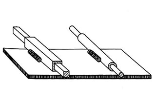
In welding processes, a cooling rod is often used to prevent burning through. When a solid round bar is inserted into a thin-walled tube or a solid rectangular bar is inserted into a rectangular tube, the heat is absorbed by the solid bar and prevents the thin-walled workpiece from burning through.
Usually, a solid round or rectangular bar is tightly installed in most hollow or rectangular pipe materials. When welding, it’s important to keep the weld away from the end of the pipe as this area is the most vulnerable to burning through.
Figure 1 shows a schematic diagram of how a built-in cooling rod can be used to prevent burn-through.
Fig1. Use the built-in cooling rod to avoid burning through
1.1.4 When it is necessary to weld a galvanized or chromium containing material to another part, what should be done?
The best practice is to file or grind the area around the weld prior to welding. This is because galvanized or chromium-containing metal sheets can pollute and weaken the weld, and also release toxic gas during welding.
1.2 Welding of vessel and frame structure
1.2.1 If a welding process (such as brazing) is used to seal a buoy or the end of a hollow structure, what will be done to prevent hot air from entering the vessel and causing the vessel to burst during the final sealing of the weld?
③ Firstly, a pressure relief hole with a diameter of 1.5mm is drilled on the pontoon to facilitate the circulation of hot air and external air near the weld. Then, the sealing welding is carried out, and finally, the pressure relief hole is sealed by welding.
Figure 2 shows the schematic diagram of a sealed welding pontoon or closed vessel.
Fig.2 Schematic diagram of narrow welding pontoon or closed vessel
While welding the gas storage vessel structure, the pressure-reducing hole can be utilized. However, it is crucial to note that welding in a closed container is highly dangerous. Prior to welding, it is essential to clean the interior of the container or pipe and avoid any flammable or explosive materials or gases.
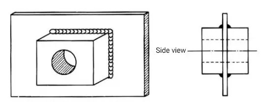
When it comes to welding the screen, wire mesh, or extended metal to the steel structure frame via GMAW, FCAW, or TIG, the wire mesh is prone to burning through, and the weld may not fuse properly during the process. To handle this issue, non-metallic washers must be placed on the wire mesh or extension metal, and the washer, wire mesh, and frame should be clamped together.
It is important to note that chromium-containing or galvanized washers are not permitted, and the washer must be uncoated as depicted in Fig. 3(a).
Fig3. Welding sketch of wire mesh and frame structure
② To serve as a heat sink, a larger washer is positioned on top of the washer at the welding location.
The upper washer should have a larger hole than the lower washer to prevent them from being welded together.
Subsequently, plug welding is performed through the two holes in the gasket, ensuring that the weld is in the lower part of the gasket.
The operator can use alternative heating methods while being cautious to prevent the surrounding grid or wire mesh from burning through, as illustrated in Figures 3 (b) and (c).
③ Another technique involves using a metal strip with a hole, aligning it with the welding position, placing the heat sink washer, and then performing plug welding, as demonstrated in Figure 3 (d).
Related reading: Wire Mesh Weight Calculator
1.3 Repair of welded components
1.3.1 In addition to the commonly used screw opener, what other methods can be used to remove damaged or rusted screws?
Two methods are introduced here:
① If the installed screw will not be damaged during heating, the nut and its assembly can be heated using an oxygen-acetylene torch until it turns red hot. Then, rapidly quench it with water to facilitate the removal of the screw. This process may require several heating and cold quenching cycles.
② If the screw groove, nut, or alveolar is damaged or lost, place a nut on the upper or remaining part of the screw head, tighten the nut, and then fill the metal inside the nut and screw using any welding method. This method will connect the nut and remaining part of the screw, providing a new grip point. Heat can also be used to fasten the screw.
The residual part of the fixed screw can be removed by welding, as shown in Fig. 4.
Fig.4. Removal of the remaining part of the set screw by welding
1.3.2: How to Repair and Reinforce a Worn Crankshaft by Welding?
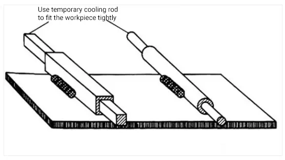
When repairing a worn crankshaft, various welding methods like GMAW, FCAW or TIG can be utilized. However, in order to achieve a satisfactory bead shape, the following four requirements should be carefully considered:
① Ensure that the bead direction is parallel to the crankshaft axis.
② Initially, a weld bead should be overlaid on the lower part of the crankshaft, and then the subsequent weld bead should be overlaid by rotating the crankshaft 180 degrees to balance welding stress and significantly reduce welding thermal deformation.
Note that sequential surfacing on the first pass can lead to crankshaft warpage. This surfacing process is appropriate for repairing and welding roller crankshafts.
③ Maintain 30% – 50% overlap of deposited metal between two welding passes to ensure a smooth surface of the welding pass during machining after welding repair.
④ While using manual arc welding and flux-cored wire gas-shielded welding, the residual flux between welding passes should be cleaned using a brush or cutting method.
Apart from the above-mentioned crankshaft repair method, a surfacing bead can be added at every 90° position of the crankshaft to further minimize welding deformation. In repairing bronze or copper parts, adding brazing metal is more advantageous in relieving stress and deformation than surfacing.
Figure 5 illustrates how to repair a worn crankshaft by welding.
Fig.5 Schematic diagram of repairing worn crankshaft by welding method
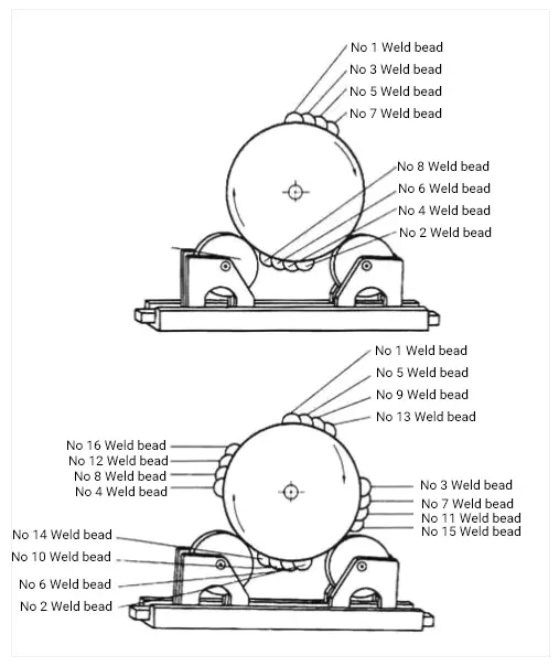
1.3.3 How to Remove a Stuck Steel Bearing from Equipment Using Welding?
To remove a stuck steel bearing from equipment using welding, first, a weld bead should be created on the inner surface of the bearing. The stretch force of the weld bead will reduce the diameter of the bearing, and the heat generated during welding will help move the bearing.
For instance, if the inner surface of a 10cm diameter pipe is covered with a weld bead, the diameter of the steel pipe will shrink by 1.2mm. Refer to Figure 6 for a schematic diagram of the welding method for removing stuck bearings.
Fig.6 Schematic diagram of removing stuck bearing by welding method
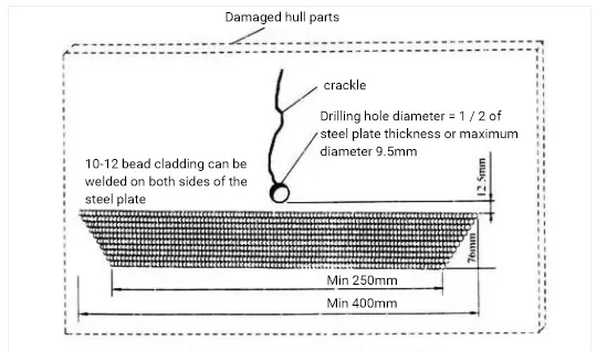
1.3.4 Cracks often occur in the structure of oil tanks or ship plates. How can we prevent them?
One method is to drill a small hole at the end of the crack to disperse the stress in a larger area, and then weld a series of multi-channel welds with varying lengths to increase the strength of the steel plate at the front of the crack.
Figure 7 illustrates how to prevent the propagation of cracks in steel plates.
Fig.7 Prevention of crack propagation in steel plate
2. Welding of reinforcing plate
2.1 Positioning and thickening of reinforcing plate
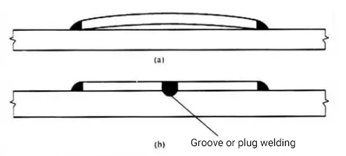
2.1.1 The reinforcing plate for welding is often welded onto the surface of the base plate.
However, the fillet weld on the outer edge of the reinforcing plate can cause the central part of the reinforcing plate to tilt up, resulting in angular deformation that separates it from the surface of the base plate. This issue is illustrated in Figure 8 (a) and can complicate machining and turning processes.
To address this problem, plug welding or groove welding can be utilized on the middle section of the reinforcing plate. This allows the surface of the reinforcing plate to closely adhere to the surface of the base plate, thus eliminating deformation and facilitating machining.
Figure 8 (b) depicts a schematic diagram that demonstrates the positioning of the reinforcing plate using plug welding or groove welding.
Fig.8 Schematic diagram of positioning reinforcing plate by plug welding or groove welding
2.1.2 Sometimes it is necessary to increase the thickness of a substrate in a specific area, but the thickened region should not exceed the overall size of the substrate. How can this issue be resolved?
One solution is to embed a thick metal plate in the section of the base plate that needs to be thickened, and then secure it by welding.
Figure 9 illustrates a thick plate embedded in the substrate.
This technique can supply enough thickness for future machining, boring, or drilling operations and can substitute bulky parts or castings in equipment.
Fig.9 Schematic diagram of inserting thick plate into the base plate
2.1.3 What is the standard method to enhance the rigidity of a slab to carry the load?
The standard method to enhance the rigidity of a slab to carry the load is to weld a series of vertical angle steels onto the slab and add angle steel stiffeners to increase its rigidity, as shown in Figure 10.
Fig.10 Schematic diagram of adding angle steel reinforcement to enhance the rigidity of the flat plate
2.2 Noise and vibration control
2.2.1 What technical measures can be used to reduce the noise and vibration of the metal plate?
The problem of noise is closely related to that of vibration, and both can be addressed by reducing the resonance frequency of the metal plate.
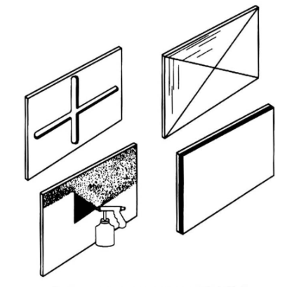
The main methods used for reducing noise and vibration are as follows:
① Increasing rigidity by folding, crimping, or groove strengthening;
② Cutting the flat plate into smaller pieces to enhance support;
③ Applying surface spray coating;
④ Bonding a layer of damping fiber material to the surface of the flat plate.
Figure 11 illustrates the four methods for increasing the resonance frequency to reduce noise.
Figure 12 shows that metal stiffness is usually increased to reduce vibration at relatively low frequencies.
Fig.11 Increasing resonance frequency to reduce noise
Fig.12 Schematic diagram of increasing metal stiffness to reduce vibration
2.2.2 If two flat plates are to be fillet welded together in the vertical direction using a C-shaped fixture, how should the welding be performed?
During the welding process, a steel block or rectangular object can be used as an auxiliary tool to assist with clamping the fillet weld. The C-shaped clamp and rectangular block can be used to secure the plates, as illustrated in Figure 13.
Fig.13 Schematic diagram of using C-shaped clamp and rectangular block to clamp fillet weld