Brazing 101: Everything You Need to Know for Beginners
Have you ever wondered about the science behind joining metals without melting them? Brazing is a fascinating process that connects metals using a filler material heated to a specific temperature range. In this article, we’ll dive into the world of brazing, exploring its characteristics, advantages, and various types. Join us as we uncover the secrets of this essential metalworking technique and discover how it shapes the products we use every day.
The brazing filler metal is heated to an appropriate temperature, typically above 450°C.
This temperature is higher than the liquidus temperature of the filler metal but lower than the solidus temperature of the base metal.
This heating process promotes wetting of the liquid filler metal on the surface of the base metal and enables the filler metal to fill the brazing joint through capillary action, thus forming a connection between two materials, which may be the same or different.
Brazing characteristics
(1) The melting point of the filler metal is lower than that of the base metal, ensuring that the base metal remains intact during the brazing process.
(2) The composition of the filler metal is significantly different from that of the base metal.
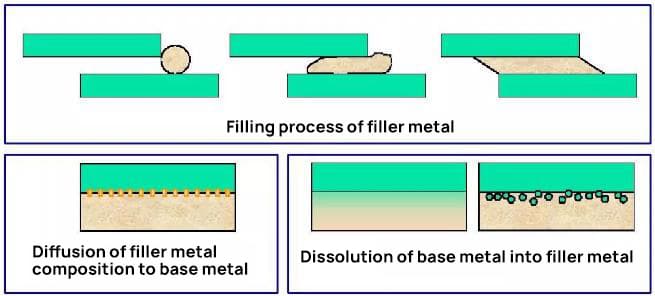
(3) The melted filler metal is drawn into and retained in the gap between the base metal components through wetting and capillarity.
(4) The metal bond is established through the mutual diffusion of the liquid filler metal and the solid base metal.
Decomposition of brazing process
Brazing advantages and disadvantages
Brazing advantages:
The brazing temperature is lower than that of the base metal, causing minimal impact on its structure and properties.
The brazing process results in minimal stress and deformation, making it an ideal choice for connecting high-precision and complex parts or structures.
The brazing process is highly efficient and can produce many joints at one time.
Brazing has a wide range of applications and can be used to join metal, non-metal, and dissimilar metals.
The brazed joint surface is of high quality.
Brazing disadvantages:
The joint has low strength and is not resistant to heat;
The multi-purpose lap joint is wasteful in terms of metal usage, adds weight to the structure, and is prone to causing stress concentrations;
There are high requirements for preparation before welding, particularly in terms of surface quality and assembly joint clearance;
Certain brazing process methods require a large investment and have high costs.
Types of Brazing
1) Classification according to solder melting point
Below 450 ℃ – Soldering
Above 450 ℃ – Brazing
2) By brazing temperature
High temperature brazing
Medium temperature brazing
Low temperature brazing. (relative)
High temperature brazing above 800 ℃; 550~800 ℃ is medium temperature brazing;
Low temperature brazing is conducted when the temperature is lower than 500 ℃.
Liquidus: the lowest temperature at which solder is completely liquid;
Solid phase line: the highest temperature at which the filler metal is completely solid;
Wetting effect:
Adhesion is the phenomenon that occurs when a liquid and a solid object stick together after coming into contact.
It can be categorized into immersion wetting, adhesion wetting, and spreading wetting.
In a free state, a liquid will attempt to maintain a spherical shape.
When the liquid comes into contact with a solid, if its cohesion is greater than its adhesion, it will not stick to the solid surface without wetting.
However, if the adhesion of the liquid is stronger than its cohesion, it will be able to adhere to the solid surface once wetting occurs.
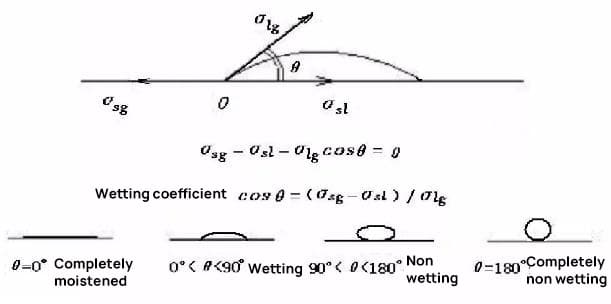
The ability of a liquid to stick to a base metal can be measured by the contact angle between the liquid and solid phases.
During brazing, the filler metal’s wetting angle should be less than 20°.
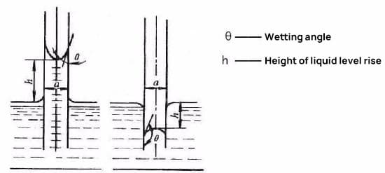
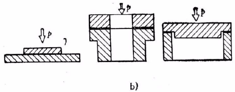
Capillary action:
It is assumed that when two metal plates that are parallel to each other are inserted vertically into an infinite amount of liquid solder, the plates are infinite and the amount of solder is unlimited.
Depending on the wetting properties of the solder on the metal plates, the capillary effect will result in either the situation shown in Figure (a) or the situation shown in Figure (b). If the solder is able to wet the metal plates, the outcome depicted in Figure (a) will occur; if not, the outcome in Figure (b) will occur.
Brazing filler metal-Soldering
Sn based and Pb based soft solders:
They have good wetting and spreading ability for copper and other metals, and are most widely used in the electronic industry.
Cd based solder:
Mainly cadmium silver alloy, with good heat resistance and corrosion resistance.
Zn based solder
Au based soft solder
Other low melting point soft solders.
Include:
① In (indium) based solder
② Bi (bismuth) base solder
③ Ga (gallium) based solder
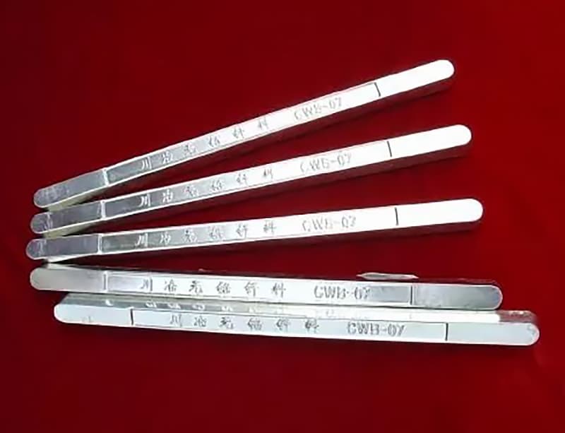
Lead-free solder
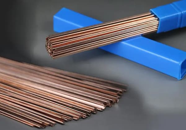
Brazing filler metal-Brazing
Due to its relatively high strength, brazing filler metal can be used to braze stressed components.
Function and performance requirements of brazing flux:
1) Remove the oxide film to create conditions for wetting and spreading;
2) The liquid flux covers the base metal and the solder surface for protection;
3) It plays an interface active role to improve wetting and spreading.
Necessity of removing film during brazing
The oxide film present on the metal surface significantly impacts the wetting and spreading of solder, and must therefore be removed.
The thicker the oxide film, the stronger its bond with the metal matrix, and the higher its thermal and chemical stability, making it more difficult to remove.
Removal can be achieved through the use of solder flux, a gas medium, mechanical methods, or physical methods.
Solder flux not only prevents the oxidation of the workpiece and solder, but also removes the oxide film. It also reduces the surface tension, promoting the flow of the solder and facilitating the formation of the solder joint.
Table 1 Formation Rate of Oxide Film in Dry Air
Metal
1 minute
1 hour
1 day
Stainless steel
10
10
10
Iron
20
24
33
Aluminum
20
80
100
Copper
33
50
50
Thickness of oxide film (10-8 cm)
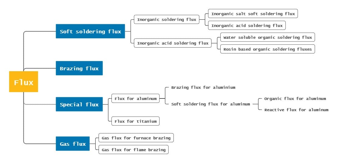
Flux classification
Brazing gas medium and its function
In brazing, the neutral gas used is mainly argon, with nitrogen being used in some cases.
Argon is an inert gas that primarily serves to protect the workpiece, and does not have the capability to directly remove the oxide film.
Some oxide films can be removed through the decomposition of oxides and the reduction, dispersion, and dissolution of the oxide film’s strength through the adsorption of liquid solder.
As shown in the table, the decomposition temperature of most metal oxides is higher than the melting point or even the boiling point of the metal.
It can be concluded that during the brazing process, it is not possible to achieve oxide decomposition simply through heating.
Oxide
Decomposition temperature (℃)
Oxide
Decomposition temperature (℃)
Au2O
250
PbO
2348
Ag2O
300
NiO
2751
Pt2O
300
FeO
3000
CdO
900
MnO
3500
Cu2O
1835
ZnO
3817
Brazing method and process
Brazing method
1. Iron soldering
Features: low temperature
Scope of application:
1. It is applicable to soldering (using tin lead or lead based filler metal) with soldering temperature lower than 300C;
2. Solder flux is required for brazing thin and small parts.
2. Torch brazing, torch soldering
Features: simple, flexible and widely used
Scope of application: generally, neutral flame or slight carbonization flame/general gas torch or special brazing torch (torch can also be used for soft soldering) shall be used to heat the workpiece first:
1. It is applicable to brazing some weldments which are limited by the shape, size and equipment of weldments and cannot be brazed by other methods
2. Automatic flame brazing can be used
3. Weldable steel, stainless steel, hard alloy, cast iron, copper, silver, aluminum, etc. and their alloys
4. Common filler metals include copper zinc, copper phosphorus, silver base, aluminum base and zinc aluminum filler metals
3. Dip brazing, dip soldering
(Salt bath and metal bath, suitable for mass production)
(A variety of metal bath brazing, mainly used for brazing printed circuit boards)
5. Resistance brazing
Extremely fast heating and high productivity.
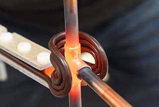
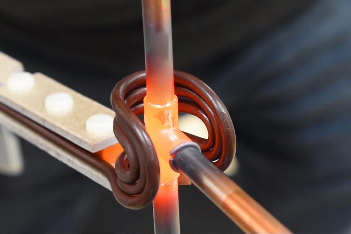
6. Induction brazing
Fast heating, less oxidation and small brazing.
Brazing techniques
The brazing production process encompasses several steps including preparation of the workpiece surface prior to brazing, assembly, placement of the filler metal, brazing, post-brazing treatment, and other related processes.
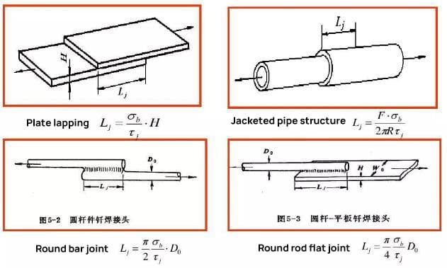
1. Brazed joint design
When designing a brazed joint, the primary consideration should be its strength, followed by the process considerations such as ensuring the dimensional accuracy of the assembly, proper assembly and positioning of the parts, placement of the solder, and the clearance of the brazed joint.
The lap joint is commonly used for brazing joints.
In practical production, for brazing joints made with high-strength silver-based, copper-based, or nickel-based filler metals, the lap length is typically 2-3 times the thickness of the thinner piece.
For soldered joints made with soft solders such as tin-lead, the lap length can be 4-5 times the thickness of the thinner piece, but it should not exceed 15mm.
Before the brazing process, it is crucial to thoroughly remove any oxide, grease, dirt, and paint from the surface of the workpiece.
In some cases, it may be necessary to pre-coat the parts with a specific metal layer prior to brazing.
(1) Remove oil stain
Oil stains can be removed using organic solvents.
Common organic solvents include alcohol, carbon tetrachloride, gasoline, trichloroethylene, dichloroethane, and trichloroethane.
(2) Oxide removal
Before brazing, the oxide films on the part surface can be processed using mechanical methods, chemical etching methods, and electrochemical etching methods.
3. Assembly and fixing
Solder metals are used in various brazing methods, with the exception of flame brazing and soldering iron brazing, most of which are pre-placed on the joint. The gravity and capillarity of the gap should be utilized as much as possible to encourage the filler metal to fill the gap when placed.
Paste filler metal should be directly applied to the brazed joint, and the powder solder can be mixed with an adhesive before being applied to the joint.
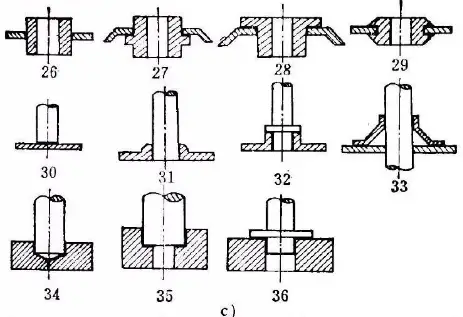
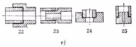
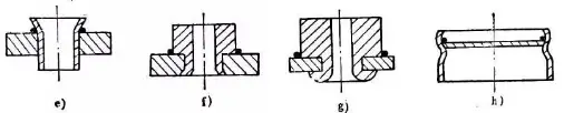
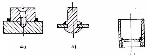
4. Placement method of filler metal
a) Placement of annular solder
1, 2 – Reasonable placement of one ring shaped materials
3, 4 – Placement to prevent loss along the flange plane
5, 6 – Placement of filler metal close to the joint
As the founder of MachineMFG, I have dedicated over a decade of my career to the metalworking industry. My extensive experience has allowed me to become an expert in the fields of sheet metal fabrication, machining, mechanical engineering, and machine tools for metals. I am constantly thinking, reading, and writing about these subjects, constantly striving to stay at the forefront of my field. Let my knowledge and expertise be an asset to your business.
Welding symbols may seem like a foreign language, but mastering them is crucial for effective communication in the world of mechanical engineering. In this blog post, a seasoned mechanical engineer…
Ever wondered how skyscrapers stand tall or cars stay welded together? This blog uncovers the magic behind electric welding machines. Learn about top manufacturers like Lincoln Electric and Miller Welds,…
Have you ever wondered how the sleek cars, sturdy bridges, and advanced airplanes of today are built? This article explores six cutting-edge welding technologies that are revolutionizing manufacturing, from laser…
Have you ever wondered why some welded structures fail unexpectedly? This article explores the hidden forces at play—welding stress and deformation. Learn how these stresses impact strength, stability, and accuracy,…
Have you ever wondered how to calculate the consumption of welding rods accurately? In this blog post, we'll explore the methods and formulas used by industry experts to estimate welding…
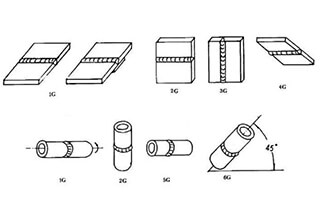
Have you ever wondered about the art of welding and the different positions involved? In this fascinating blog post, we'll delve into the intricacies of welding positions, from flat to…
Ever wondered what "X-weld" or "tack-weld" means? Our latest article breaks down 292 crucial welding terms, offering clear definitions and practical examples. Whether you're a seasoned welder or just starting,…
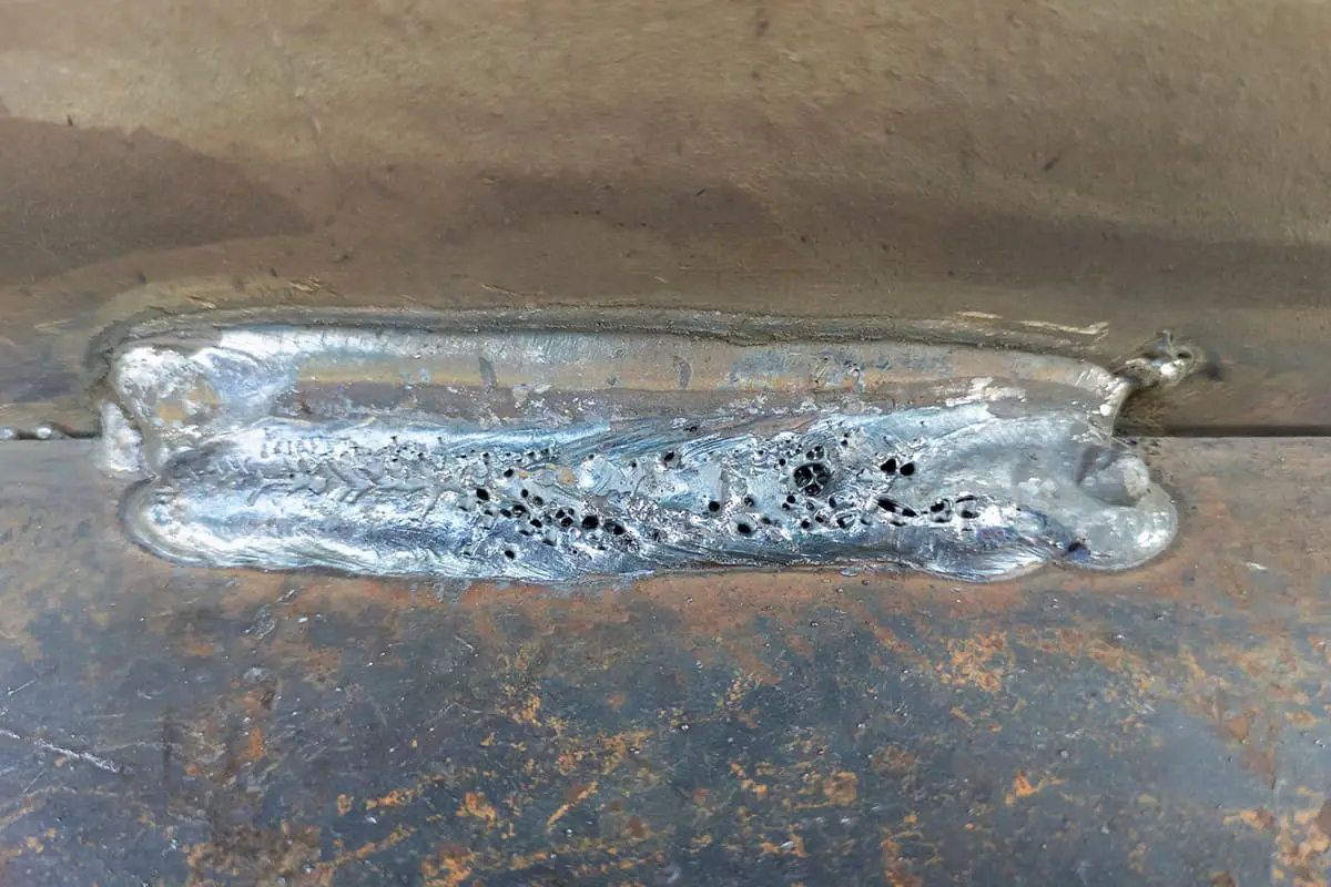
Why does argon arc welding sometimes produce pores, and how can we fix it? Welding porosity, often caused by impurities, improper gas flow, or incorrect technique, can weaken welds and…
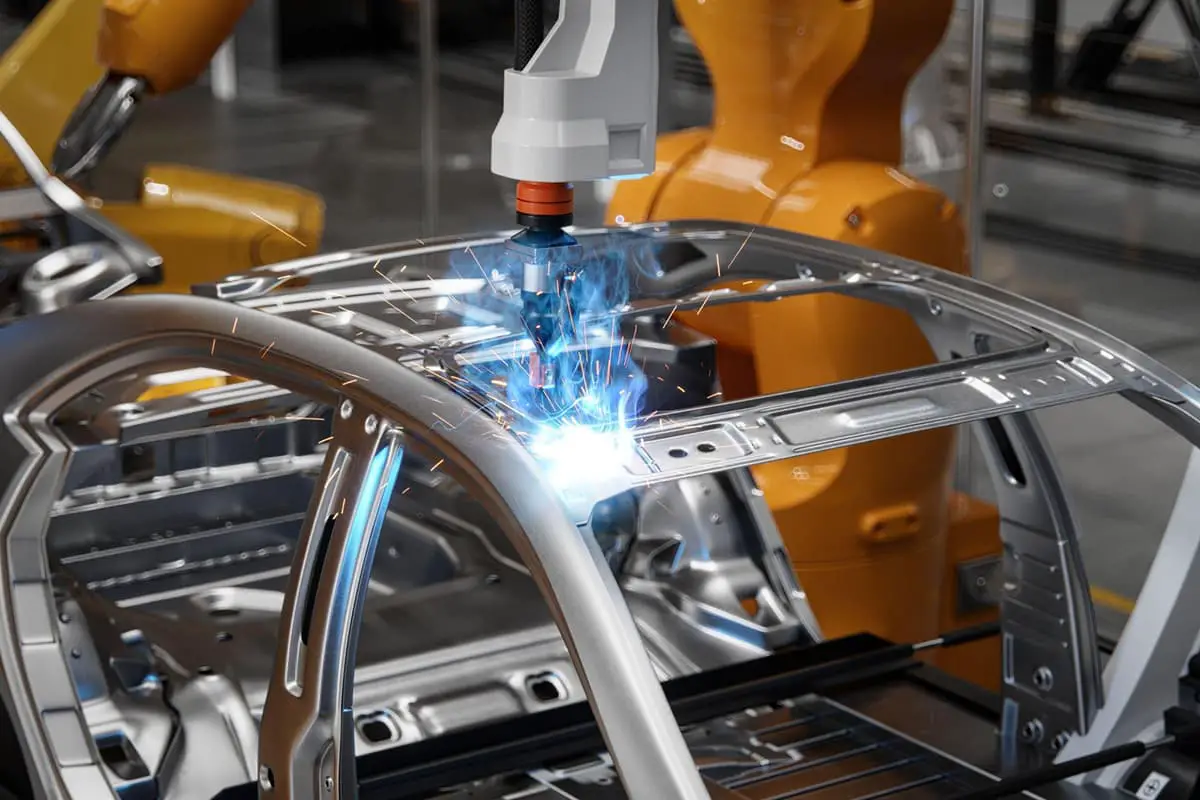
Imagine a machine that welds with precision, never tires, and enhances safety in industrial settings. This article explores the fascinating world of arc welding robots, detailing their components, operational procedures,…