The development progress of the mold plays a crucial role in the entire project’s schedule and is an important part of the OEM’s production preparation.
In the following paragraphs, we will discuss the process and schedule control of mold development, from body data release to final mold inspection and acceptance.
1. Release of Body Process Data
The body design department releases product simulation models, and the engineering personnel of the engineering development department perform process analysis and quotation based on the product simulation models (as comparative data for bidding).
The body process simulation model is used for mold bidding and corresponding process analysis. The bidding process will not be discussed in detail here. Below, we will talk briefly about mold development management after finalizing the mold factory.
2. Feasibility Analysis of Body Part Manufacturing Process (Mold Developer and Engineering Development Department)
After receiving the body process simulation model, the mold developer conducts a feasibility analysis of each part’s manufacturing process. In principle, mold factories are required to conduct CAE analysis (i.e., simulation analysis of part formability) on all newly developed parts.
The role of CAE analysis:
- Through CAE analysis, we can observe the forming process of sheet metal more intuitively.
- Shorten the cycle of mold design and analysis.
- Predict the possibility of mold.
- Adopt optimized design to minimize the consumption of molds and steel materials, reduce manufacturing costs.
- Identify potential risks of molds and parts before manufacturing.
- Ensure the rationality of mold design and reduce design costs.
- Based on the potential problem analysis of the parts, the mold factory can propose reasonable design change suggestions in a timely manner, and promote the development work more efficiently.
The development department can fully utilize the experience of on-site production debugging and check whether the process parameters and the supplementary stretching are reasonable based on the CAE analysis results of the parts provided by the mold factory.
In response to risks such as wrinkling or cracking of the parts, the department can propose solutions in a timely manner.
3. Design and Co-sign of DL Diagram
After the CAE analysis is completed, the mold DL diagram design can be conducted in most cases.
DL diagram design refers to the stamping process analysis and design, also known as the mold process flowchart, which includes the size of the part sheet, the direction and angle of stamping, the arrangement of stamping processes, the feeding direction, the distribution and direction of scrap knives, the illustration of scrap removal direction, CH hole, left and right part identification, and labeling of each process.
In addition, the DL diagram must also reflect the stamping equipment for relevant processes, mold height, mold material, the working stroke of edge pressing rings or press plates, the positioning method of sheet metal, and pressure analysis of the completed process.
After the DL design is completed, internal auditing should be carried out in the mold factory. Once the internal audit issues are rectified, the design can be provided to the OEM’s development department and co-signed.
The co-sign of the DL diagram is critical, directly affecting the later mold design and having a significant impact on the mold development cycle and cost. If the DL diagram is changed later, it will cause considerable waste in terms of development cycle and cost.
The engineering development department mainly reviews the rationality of part process, correctness of machine parameters, rationality of process supplement, material utilization rate, and examines the convenience of feeding in conjunction with the press situation.
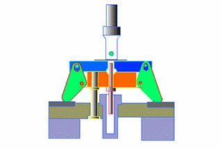
4. Mold Structure Diagram Design and Co-sign
The co-sign order of mold structure diagrams: co-signing of stretching mold diagram – co-signing of forming flange mold diagram – co-signing of edging and punching mold diagram.
As the casting and processing cycle of the mold is inflexible, it is important to ensure the project’s progress by designing the mold structure diagram stage as early as possible to gain additional time for the subsequent mold manufacturing.
Generally, the mold’s first sampling is a semi-manual sample, only requiring forming, while the remaining edging and punching can be completed by wire cutting.
Therefore, the design of stretching mold and forming flange mold diagrams should be carried out before designing the edging and punching mold diagram.
The mold factory designs the mold structure diagram based on the DL diagram guidance, and after completion, it is also subject to internal review. After addressing any issues found during the review, it can be presented to the OEM’s development department for co-signing.
The OEM’s development department should focus on:
- Mold functionality
- Structural stability and strength
- Mold production safety
- Consistency of mold parameters with mass production presses
- Convenience of debugging and production
- Consistency of material for major mold components with technical protocol requirements
For problems discovered during the review, the mold factory should be requested to rectify them as much as possible. Some issues may not have a significant impact on product functionality but may affect operational convenience or reduce production efficiency. To meet deadlines and schedules, the mold factory may not be too cooperative in making changes.
At this point, the OEM’s development personnel (engineers) need to show courage and determination because changes during the design phase are always faster than changes later (after the mold has been formed).
Designers at the mold factory need to think from the perspective of the production department and consider the problem from multiple angles.
Disputable problem points require objective discussion among many parties to find the best solution. During the mold diagram review process, engineering development technicians are required to have a firm stance and solid technical and on-site debugging experience to reduce many problems later.
5. Release of Casting Numerical Model and Evaluation and Rectification of Foam Realistic (EPS) Model
After the mold structure diagram design review, foam realistic models can be made. In the foam realistic model stage, the project team needs to release casting data to ensure the castability of the real model.
The foam realistic model is a material formed by high-temperature foaming of polystyrene. It is processed by NC based on the mold structure diagram and considering appropriate mold processing allowances (8-10 days) and foam shrinkage rate.
The production cycle of EPS foam is generally around one week. After production, it needs to undergo on-site evaluation to ensure consistency with the mold structure diagram.
It also checks whether the problems identified in the mold structure diagram review have been rectified or any new issues that were not discovered during the design review.
The evaluation of foam realistic models is an indispensable process in mold making because it is the last hurdle for mold structural changes. Once it has entered the casting phase, it is difficult to modify the mold structure.
6. Mold Casting
After the EPS foam has been rectified, it can be shipped to the foundry for casting. The specific process will not be discussed here. The mold casting cycle is 15-20 days. After the mold casting is complete, it is transported back to the mold factory for casting inspection.
The main focus is on checking for major casting defects, such as cracks inside the casting. Internal defects such as sand inclusion need to be machined before they can be observed.
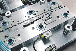
7. Release of NC Numerical Model and NC Machining of the Mold
After mold casting is complete, NC machining can begin, provided that the NC data has been released.
The mold factory can perform CNC programming based on the product’s NC data and then carry out NC machining of the mold. Mold NC machining can be roughly divided into: rough milling – assembly – semi-finishing – finishing.
During the NC machining process, defects such as sand inclusion or cracks inside the casting can be detected. After NC machining is complete, the mold needs to undergo heat treatment to achieve the required hardness.
The mold’s NC machining cycle is generally 20-25 days.
In situations where project development time is tight, it is important to arrange NC machining time reasonably. Engineering development personnel can perform on-site progress control and supervise the mold factory in developing a reasonable machining plan.
It is important to avoid keeping the CNC machining equipment idle to ensure progress.
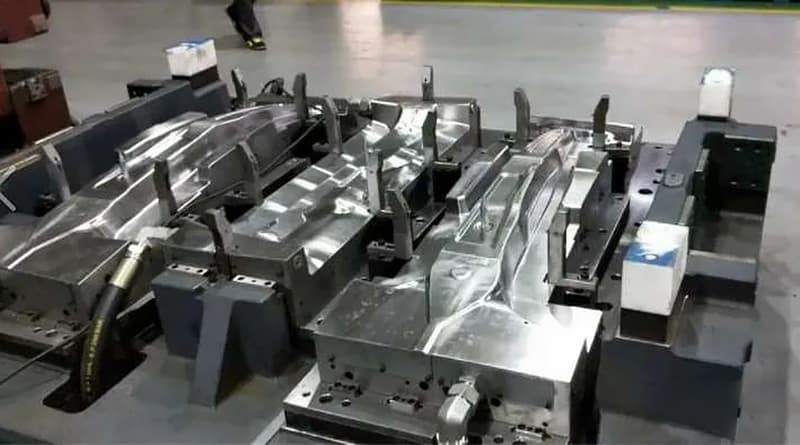
8. Mold Fitter, Debugging, and Sampling Process
The mold fitter stage includes: mold base alignment – mold closing – trial molding – sampling, etc. After the mold is NC machined, there is still a certain allowance for subsequent fitting.
Mold fitter debugging mainly checks the matching rate of the upper and lower molds and the guiding rate to ensure that qualified stamped parts are produced.
Through mold fitter debugging, the quality of the mold can be identified, and the size for cutting can also be determined.
9. Mold Pre-Acceptance
After the mold factory completes all the mold making according to plan and self-tests the mold to be qualified, it can apply for pre-acceptance from the OEM’s development department.
The mold factory needs to provide a self-inspection report on the mold and the qualification rate of the stamped parts. The OEM’s development department organizes personnel to conduct pre-acceptance at the mold factory after receiving the mold factory’s pre-acceptance application.
The mold is mainly accepted from three aspects: mold statics, dynamic stamping part quality, and mold function.
Static and dynamic inspections are carried out according to standards, while stamping part inspection is divided into surface quality, dimensional accuracy, and stiffness.
In principle, problems found during the pre-acceptance process require rectification by the mold factory before packaging and shipping.
However, if some problems do not affect the product quality and the difficulty of rectification is small, they may be allowed to remain for the mold factory’s fitters to continue rectifying at the production site in cases where time is tight.
10. Mold Production Site Debugging and Acceptance
Due to differences in machine tools and mold surface matching rates, to ensure the quality of the product, after the mold has been pre-accepted, it needs to be debugged when transported to the production site.
Generally, the first round of stretching mold fitting takes 1-2 months, and the entire mold debugging cycle can last for half a year or longer. The mold production site debugging process revolves around the following aspects:
- The stamping parts need to be clamped in the welding fixture to verify the coordination of the mold, clamp, gauge, inspection tool, and welding fixture.
- Ensure the accuracy of the stamped parts by inspecting them on the inspection gauge. The qualification rate is generally required to be above 90%.
- Problems or defects found during the stamping of parts on the inspection gauge or feedback from the welding and debugging process should be rectified by the mold factory.
- Check the dynamic and static inspection items of the mold function.
- The mold’s reliability in continuous production on the production press, that is, the requirement for scrap rate in continuous production is less than 2%.
The mold debugging and rectification cycle is long. The above items need to be rectified, and the mold needs to be operated stably for three months before the OEM’s development department can organize the mold user, maintenance personnel, quality inspector, etc. to carry out final acceptance of the mold and sign the final acceptance report.
After completing the final acceptance, the mold development work is considered complete.
However, as long as the mold is not scrapped, the lifecycle of the mold continues. The work of the OEM’s development department is then transferred to the production system and process department for use, management, and maintenance.
With good usage and maintenance of the mold, its service life can be extended, the scrap rate reduced, and production efficiency increased, bringing considerable economic benefits to the company.