28 Sheet Metal Bending Problems and Solutions
Have you ever struggled with sheet metal bending problems that left you scratching your head? In this insightful blog post, an experienced mechanical engineer shares their expertise on tackling common…
How do you ensure precision and safety while using a press brake? This article offers 22 essential tips for optimizing press brake performance, covering topics like die selection, mold installation, backgauge accuracy, and hydraulic adjustments. By following these expert guidelines, you can enhance the efficiency and reliability of your press brake operations, ensuring high-quality bending results and prolonged machine lifespan. Dive in to learn practical steps that can significantly impact your metalworking projects.

1) Selection of the top punch
A) The choice of the top punch for the press brake is determined by the bending force and must not surpass the maximum load capacity of the die.
B) If a special die is selected, it is crucial to note that the load on these dies differs from that of a standard die.
2) Selection of the bottom die
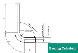
The width of the V-opening in the lower die must be determined based on the thickness (S) of the sheet material. The formula is as follows:
If S<3mm, the V-opening width should be between 6 to 8 times the thickness of the material (V = (6~8) × S).
If S>3mm, the V-opening width should be between 8 to 12 times the thickness of the material (V = (8~12) × S).
Where:
Note that the minimum bend width (b) and bend angle must be adjusted accordingly to determine the limits of the shape of the lower die scientifically.
(1) Precautions
A) The operator must observe safety principles when installing the mold in the dangerous area of the press brake machine.
B) It is not allowed to pass hand or body through the mold.
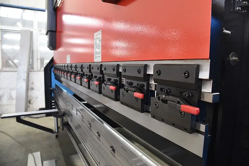
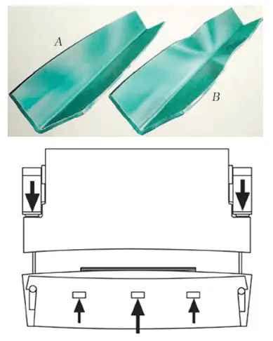
(2) Upper Mold Installation
A) Switch the machine control mode to manual mode using the key switch.
B) Activate manual control in manual mode.
C) Press the machine axis start button.
D) Step on the foot switch and let the press brake machine’s ram move down slowly until it stops at the bend conversion point.
E) Press the machine axis stop button.
F) Loosen the mold clamps to install or replace the top punch.
G) Secure the upper mold and upper mold base and slightly tighten the clamping screw or close the mold clamps.
(3) Lower Mold Installation
A) Loosen the lower die clamping screw before installing or replacing the lower die.
B) Manually align the center of the lower die opening with the center of the upper punch.
C) Press the machine axis start button.
D) Step on the pedal switch.
E) In manual position mode, manually move the hand wheel slowly to move the ram down.
F) Press the mold together with a small force, ensuring that the center of the upper mold and the center of the lower mold are on the same line.
G) After all sides of the die edge are in contact, tighten the clamping part of the upper and lower die.
A) Stop the machine.
B) Remove the rear protective cover from the machine.
C) Loosen the intermediate position of the press brake machine, or the tightening screw of the tensioning wheel located at the X-axis motor connecting plate.
D) Position the tensioning wheel correctly.
E) Tighten the tensioner set screw.
F) Replace the rear guard on the machine.
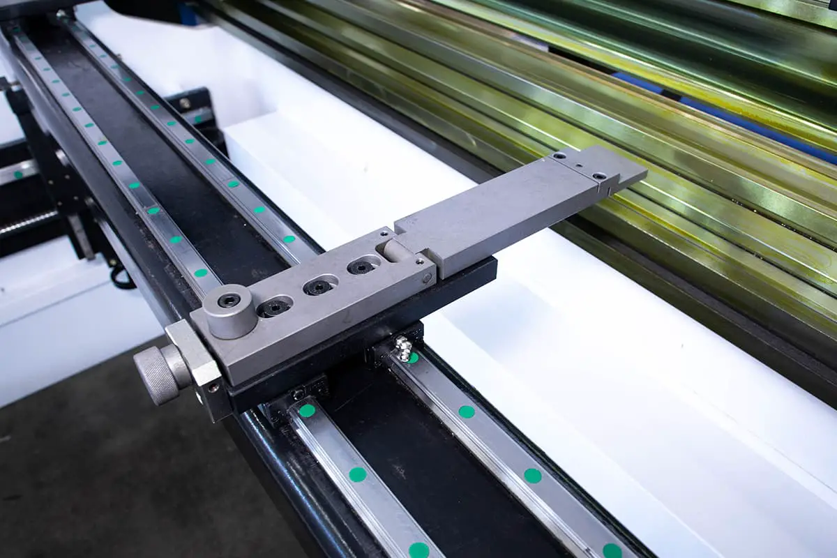
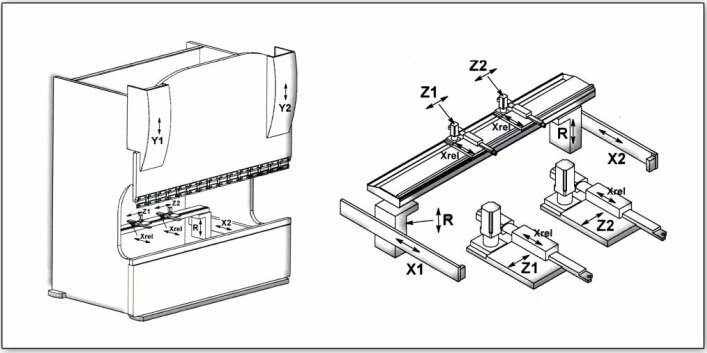
A) Verify the accuracy of the back fingers after movement.
B) Determine the error of the two back fingers using a depth gauge.
C) Align the back fingers so that the distance from each finger to the center of the lower die opening is uniform.
D) Test bend a workpiece and assess the accuracy error in the X-axis.
E) Make adjustments to the X-axis correction.
F) Test bend the workpiece again, and use it for normal bending once accuracy has been confirmed.
A) Test bend a workpiece, assess the accuracy of the X-axis, and calculate the error.
B) Lower the ram below the bend transition point in either automatic or manual mode.
C) Adjust the X-axis reference point value.
D) Once the machine tool returns to the reference point, confirm accuracy and use it for normal bending.
A) Verify that the centers of the upper and lower dies are aligned;
B) Use the top mold as a reference and use a back finger to measure the error at both ends of the X-axis beam. Do not touch the mold with your hand or body.
C) Remove the rear protective cover of the machine.
D) Unfasten the screw that secures the timing belt on the front end of the right side of the X-axis beam of the press brake machine.
E) Secure the right box connector to prevent any movement.
F) Adjust the timing belt to move the screw on the left side of the X-axis beam forward or backward as necessary.
G) Use the upper mold as the reference and measure the error at both ends of the X-axis beam with a back finger. Repeat the adjustment process until the error at both ends does not exceed 0.20 mm.
H) Tighten the screws that secure the timing belt on the right side of the box.
I) Release the fixings of the right box connector.
J) Return the machine to its reference point.
K) Test bend the workpiece and measure the accuracy of the X-axis. Calculate any error.
L) Modify the number of X-axis reference points as necessary.
M) After the machine returns to the reference point, test bend the workpiece to confirm proper and normal processing.
A) Bend the workpiece and measure the accuracy error of the Y1 and Y2 axes (based on a 90-degree bend);
B) Lower the ram below the bend transition point in either automatic or manual mode;
C) Select the Y-axis parameter;
D) Adjust the reference point position for the Y1 and Y2 axes by approximately 0.07 for each degree;
E) After the machine tool returns to the reference, bend the workpiece again to verify correct and normal processing.
A) Bend the workpiece and measure the intermediate accuracy error of the workpiece (based on a 90-degree bend).
B) In either automatic or manual mode, lower the ram below the bend transition point.
C) Select the CROWNING axis.
D) Adjust the minimum and maximum DA values based on the actual situation.
E) After the machine tool returns to the reference point, bend the workpiece again to confirm that the processing is correct and normal.
A) In either automatic or manual mode, lower the RAM below the bend transition point.
B) Adjust the X-axis gain as necessary by reducing it.
C) Once the machine tool returns to the reference point and is operating normally in dry running conditions, processing of the workpiece can begin.
A) In either automatic or manual mode, lower the RAM below the bend transition point.
B) Adjust (increase) the X-axis gain as necessary.
C) Once the machine tool returns to its reference position and operates normally under dry running conditions, processing of the workpiece can commence.
1) Adjust the backup pressure valve as follows;
A) Loosen the hex lock nut on the backup valve;
B) Adjust the pressure backup valve’s adjusting screw;
C) Check if the ram slide value is normal;
D) Process the workpiece after normal operation.
2) Clean the backup valve as follows;
A) Move the ram to the lowest position using manual mode;
B) Switch off the oil pump motor and turn off the power to the machine;
C) Detach the backup valve from the valve seat for cleaning;
D) Reinstall the backup pressure valve after cleaning;
E) Once the machine tool has returned to its reference position and is functioning properly, the workpiece can be processed.
3) Replace the backup valve as follows;
A) In manual mode, lower the ram to the bottom.
B) Turn off the power and the oil pump motor of the press brake machine.
C) Remove the backup valve from its seat.
D) Install the new backup valve.
E) Once the machine tool has returned to its reference position, properly adjust the new backup pressure valve. After a dry run has been completed and is normal, the workpiece can be processed.
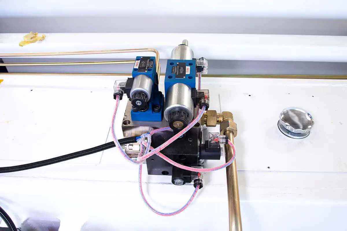
1) The ram does not move under normal conditions. First check if the circuit is normal. After confirming the circuit is normal, the servo valve can be detected as follows:
A) Input the command “Valve Test” and select it.
B) Choose either the left or right valve.
C) Turn the hand wheel to change the percentage and observe if the voltage changes.
D) If no change is observed, clean or replace the synchronous servo valve.
2) The method of cleaning the synchronous servo valve is as follows:
A) In manual mode, lower the RAM to the bottom.
B) Turn off the oil pump motor and the power of the machine.
C) Disconnect the plug of the control circuit for the synchronous servo valve.
D) Unscrew the connection between the synchronous servo valve and the valve seat.
E) Remove the synchronous servo valve and disassemble it, taking care not to break the paint seal.
F) To remove burrs, use metallographic sandpaper to smooth the valve core, ensuring that it moves freely within the valve body.
G) Clean the valve spool using gasoline. Reassemble the synchronous servo valve.
H) Secure the connection between the synchronous servo valve and the valve seat with screws.
I) Reinstall the plug for the control circuit of the synchronous servo valve.
J) After installation, test the synchronous servo valve. If it does not function properly, it is recommended to replace it.
K) Once the test is normal, return the machine to its reference position.
L) After a successful dry run, the workpiece can be processed.
The filter element of the machine must be replaced after a specified period of time, either every 6 months or after 1000 working hours, or if the pressure alert cover at the top of the filter is dropped. The steps to replace the filter are as follows:
A) Lower the ram below the bend transition point in either automatic or manual mode;
B) Turn off the power to the machine and the oil pump motor of the press brake machine;
C) Open the rear protective cover of the machine;
D) Disassemble the filter;
E) Remove the old filter element, replace it with a new one, and tighten the filter;
F) Reinstall the rear protective cover of the press brake machine;
G) Turn on the power to the machine and restart the oil pump motor;
H) Allow the hydraulic oil to filter for 1 hour;
I) The machine can now return to normal processing.
A) Reduce the RAM below the bend transition point in either automatic or manual mode;
B) Shut down the oil pump motor and the power of the machine;
C) Open the machine’s rear protective cover;
D) Disconnect the oil pipe connecting the crowning cylinder;
E) Remove the crowning cylinder guard;
F) Detach the bracket that connects the crowning cylinder and the machine frame;
G) Tap the back of the crowning cylinder with a wooden stick and remove it from the front of the machine;
H) Take out the joint on the crowning cylinder and install it on the new crowning cylinder;
I) Insert the new crowning cylinder from the front of the machine;
J) Reconnect the crowning cylinder’s oil circuit;
K) Secure the connection between the crowning cylinder and the machine frame using the bracket;
L) Attach the crowning cylinder front cover and the rear protective cover of the machine;
M) Turn on the power of the machine and restart the oil pump motor;
N) The machine should return to its reference position and be able to process normally.

A) In either automatic or manual mode, raise the ram to the top dead center and ensure it is properly supported.
B) Turn off the machine power and the oil pump motor.
C) Remove the rear protective cover of the machine.
D) Open the shut-off valve at the bottom of the tank to drain the hydraulic oil. Connect the oil pipe to the oil outlet of the valve and place the other end of the pipe into the oil receiving barrel.
E) Fill the new hydraulic oil to the middle of the oil level gauge using the oil filter and hold the ram at the top dead center position.
F) Turn on the machine power and start the oil pump motor.
G) Filter the hydraulic oil for 1 hour.
H) Lower the ram below the bend transition point.
I) Return the machine to its reference position and resume normal operation.
A) “Emergency Stop” button has been pressed.
Solution:
Reset the “Emergency Stop” button.
B) A CNC or servo alarm has occurred.
Solution:
Investigate the alarm and take appropriate action.
C) A error message is displayed on the CNC display indicating that Windows startup has not completed.
Solution:
Inspect the CNC unit to determine the cause of the issue.
D) The control circuit is unable to initialize the machine.
Solution:
Diagnose and repair any issues with the control circuit.
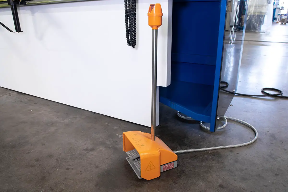
A) The footswitch is either damaged or its cable is damaged.
Solution: Replace the footswitch with a new one.
B) The process for returning is not complete.
Solution: Complete the return reference process.
C) The bottom dead point has not been set.
Solution: Set the bottom dead point.
D) The ram is not at its top dead position.
Solution: Move the ram to its top dead position.
E) The motor is not functioning.
Solution: Inspect the electrical system.
F) The control circuit is either malfunctioning or damaged.
Solution: Check the circuit and all its connections.
A) Incorrect Parameter Configuration;
Revised Solution:
Verify that the parameters are configured correctly.
B) Loose Bolt Connecting the Ram;
Revised Solution:
Inspect the connection and tighten the bolt(s) as necessary.
C) Malfunctioning Control Device;
Revised Solution:
Inspect and assess the control device to determine the issue.
A) Improper timing belt tension;
Solution:
Adjust the tension of the timing belt to the correct specifications.
B) The guide rail and the ball screw lack lubricating grease;
Solution:
Lubricate the guide rail and the ball screw to ensure smooth operation.
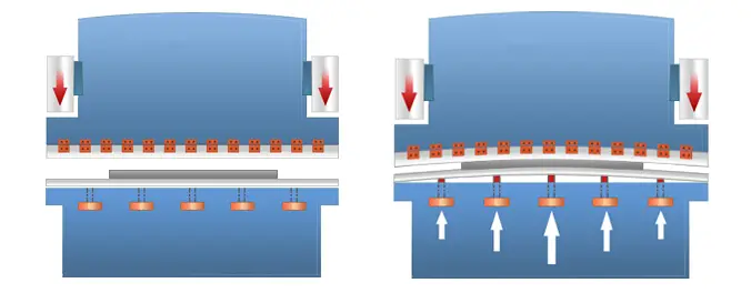
The compensation setting for the worktable crowning device is incorrect;
Revised solution:
Reset the compensation setting.
A) The pressure is too low.
Solution: Increase the pressure.
B) The ram is not parallel in the vertical position.
Solution: Check the Y-axis initial value and adjust the ram’s parallelism.
C) The mold’s parallelism is outside of the tolerance.
Solution: Adjust or replace the mold and reset the compensation amount on the work table.
D) The workpiece quality is inconsistent (e.g. varying thickness).
Solution: Use workpieces of consistent quality.
A) The pressure is too low.
Solution: Increase the pressure.
B) The holding time is insufficient.
Solution: Extend the holding time.
C) The bending speed is too slow.
Solution: Increase the bending speed.
D) The workpiece quality is inconsistent (e.g. varying thickness, changes in tensile strength, etc.).
Solution: Use workpieces of consistent quality.
E) The width of the V-opening in the lower die is too narrow.
Solution: Replace the lower die with one that has a wider V-opening.

As the founder of MachineMFG, I have dedicated over a decade of my career to the metalworking industry. My extensive experience has allowed me to become an expert in the fields of sheet metal fabrication, machining, mechanical engineering, and machine tools for metals. I am constantly thinking, reading, and writing about these subjects, constantly striving to stay at the forefront of my field. Let my knowledge and expertise be an asset to your business.