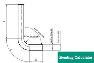
0° – 180° Bend Allowance Chart for Sheet Metal Bending
Have you ever wondered how sheet metal parts are designed and manufactured with precision? In this blog post, we'll dive into the fascinating world of bend allowance - a crucial…
Have you ever wondered how to design sheet metal parts for optimal bending? In this blog post, we’ll explore the key principles and best practices for achieving high-quality bends while avoiding common pitfalls. Drawing on the expertise of experienced mechanical engineers, we’ll delve into crucial aspects such as bending height, radius, direction, clearance, strength, and more. By the end of this article, you’ll be equipped with valuable insights to elevate your sheet metal designs and streamline your manufacturing process.
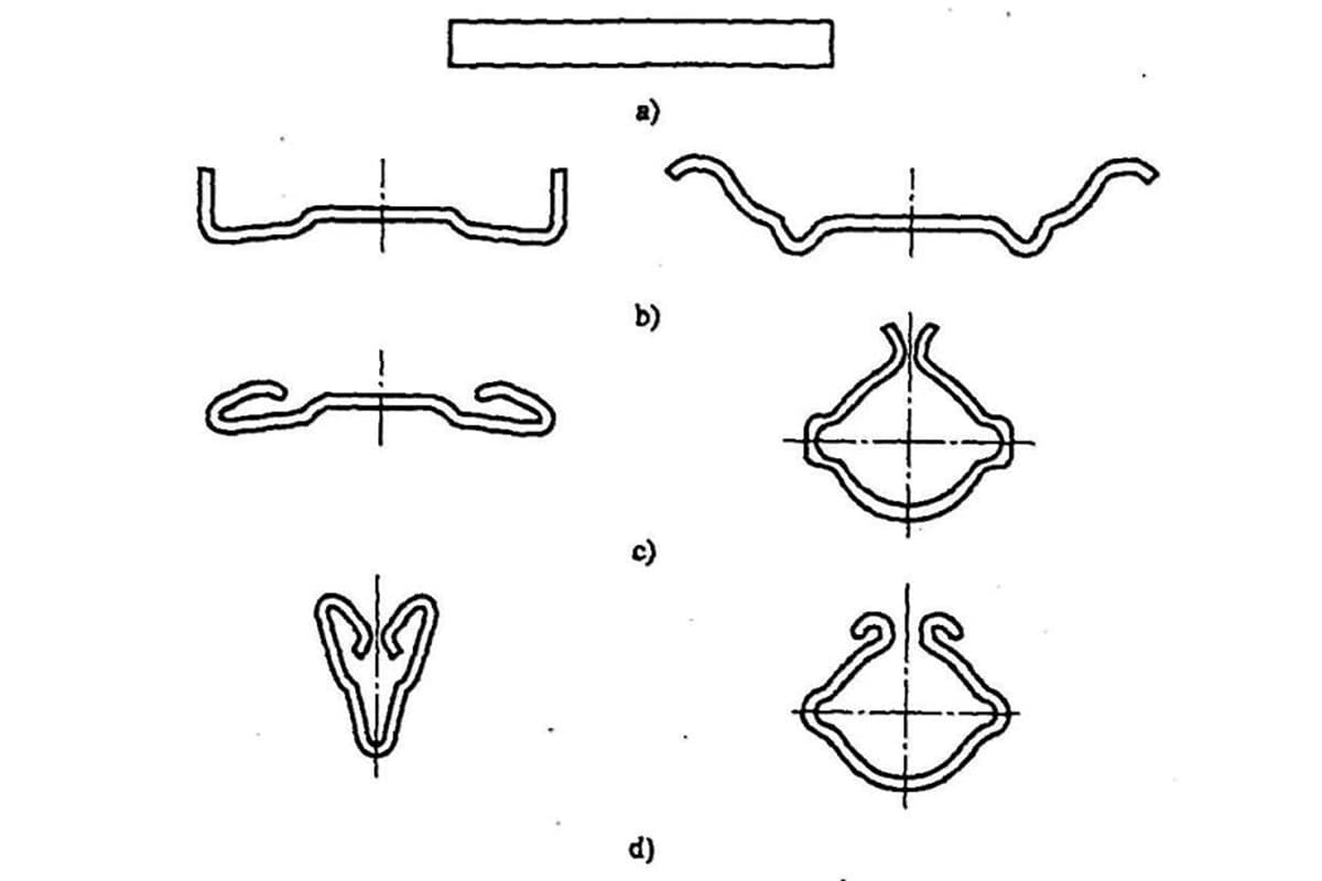
Bending is a stamping process that uses pressure to plastically deform the material, forming a specific angle and curvature shape. Common bends include V-bends, Z-bends, offset bends, and hemming bends, among others.
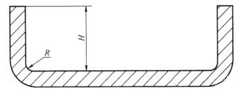
The minimum sheet metal bending height should be calculated as 2 times the thickness of the sheet metal plus the bending radius, i.e., H ≥ 2t + R.
As illustrated in the accompanying figure, if the bending height is too low, the sheet metal is prone to deformation and twisting during the bending process, leading to suboptimal part shape and dimensional accuracy.
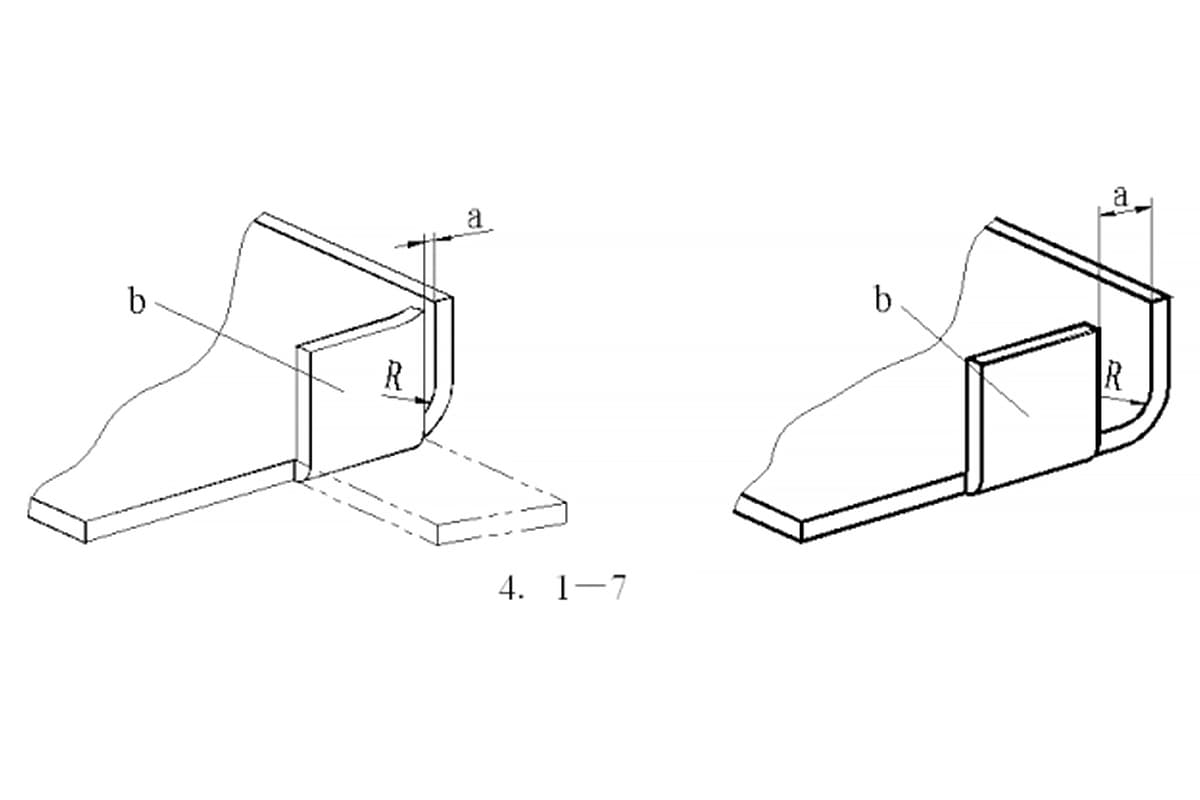
When bending a beveled edge, inadequate bending height is the main cause of bend distortion.
As depicted in the accompanying figure, in the original design, the bending height on the left is too small, which increases the likelihood of bend deformation and reduces the overall bending quality.
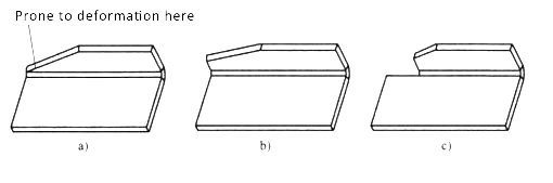
In the improved design, the height of the left-side bend can be increased, or the minimum portion of the bending height can be eliminated, ensuring that the sheet metal bend does not suffer from distortion and achieving high bending quality.
To ensure the bending strength of the sheet metal, the bending radius should be greater than the minimum bending radius specified for that particular sheet metal material. The minimum bending radii for various common sheet metal materials are listed in the table below.
| Material Condition | |||
|---|---|---|---|
| Material | Soft | Hard | |
| Aluminum alloy | 0 | 6t | |
| Bronze bronze | 0 | 4t | |
| Brass | 0 | 2t | |
| Magnesium alloy | 5t | 13t | |
| Iron | Stainless steel | 0.5t | 6t |
| Low carbon steel low alloy steel | 0.5t | 4t | |
| Titanium | 0.7t | 3t | |
| Titanium alloy | 2.6t | 4t | |
Sheet metal original and improved bending radius design as shown below:
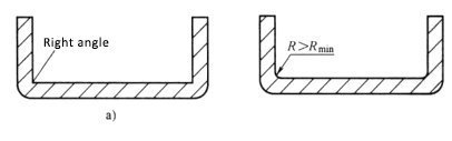
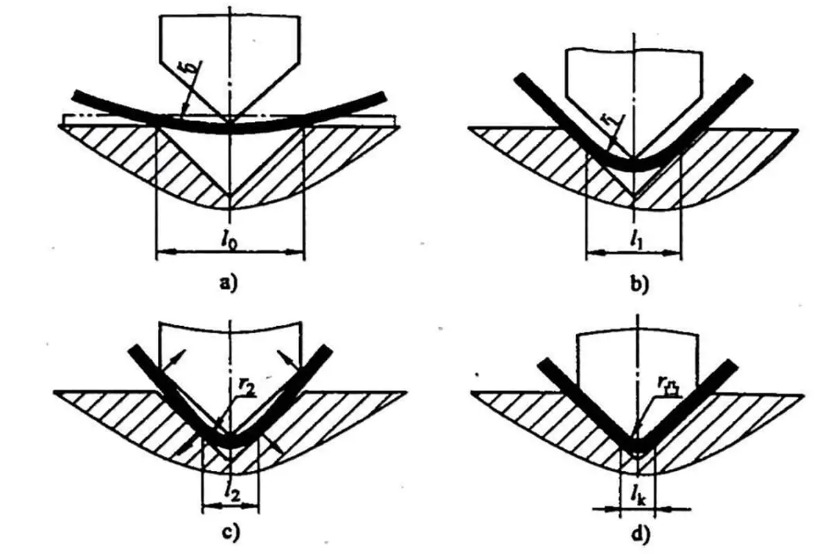
It’s important to note that a larger bending radius is not always better for sheet metal. A larger bending radius leads to larger spring back and difficulties in controlling the bending angle and height. It’s crucial to choose a reasonable bending radius.
Sheet metal mold manufacturers often opt for a bending radius of zero to avoid spring back and achieve better control over the bending height and angle. However, this can result in external cracking or even breakage of the sheet metal, especially for hard materials. Furthermore, the right angles on the mold can become rounded over time, making it challenging to maintain accurate bending dimensions.
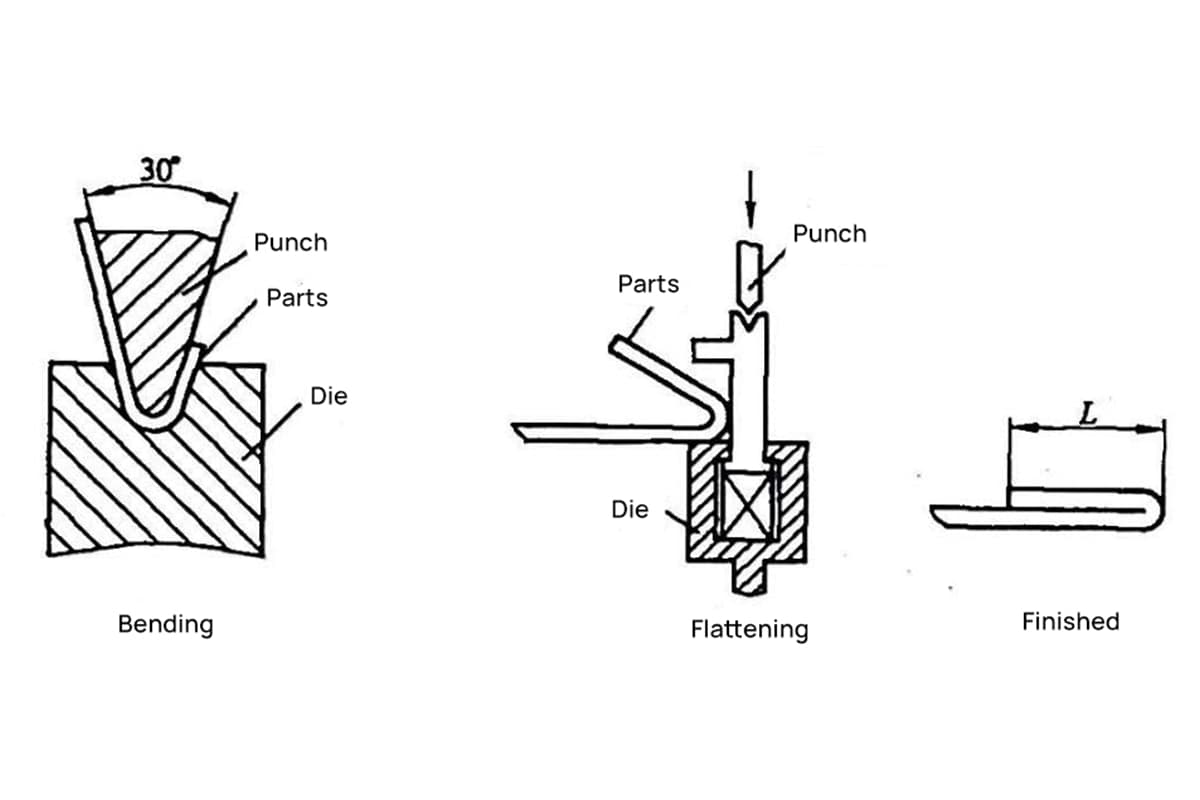
To reduce bending force and ensure consistent bending dimensions, some sheet metal mold manufacturers employ a pressing process before bending, as shown in the accompanying figure.
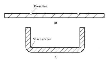
However, this design also has some drawbacks, such as low bending strength and a tendency for the sheet metal to fracture easily.
The pressing process is a type of stamping process where a partially extruded material is used to force a groove onto the sheet metal, making it easier to bend and improving bending accuracy.
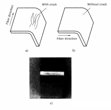
Sheet metal bending should be as close to perpendicular as possible to the direction of the metal fibers.
When the sheet metal bend is aligned with the direction of the metal fibers, it is more likely to crack at the bend and have low bending strength, making it prone to breaking, as depicted in the accompanying figure.
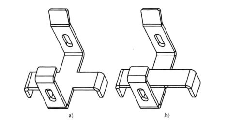
When sheet metal is bent, it’s often due to other features being too close to the base of the sheet metal, making it impossible to press and bend or causing significant deformation after bending.
To prevent this, it’s important to ensure that there are no other features blocking the pressing by keeping at least two times the thickness of the sheet metal plus the bending radius clear at the base of the sheet metal, as demonstrated in the accompanying figure.
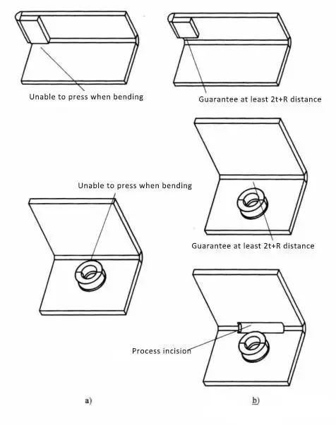
In the original design, the offset flattening position was too close to the base of the sheet metal, causing the bending process to fail because it couldn’t be pressed.
For example, if the budding on the sheet metal is too close to the root of the bend and prevents it from being made, the budding can be moved to the base of the sheet metal, as shown in the first improved design.
If the design requirements prevent the position of the bud and bend from being moved, an open cutting can be added to the root of the bend corresponding to the bud to ensure a smooth bending process, as demonstrated in the second improved design.
Due to the existence of tolerance in sheet metal bending, a certain bending clearance must be ensured in the direction of bending to avoid failure caused by interference during the bending process.
As demonstrated in the figure below, it is a simplified representation of a complex sheet metal bending part. The bending sequence involves first bending the upper side and then bending the right side.
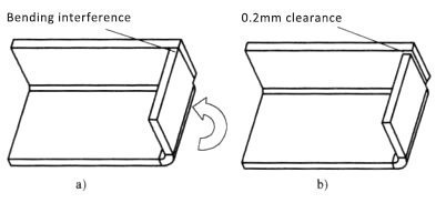
In the original design, there was no space between the two bending edges. This lack of clearance between the upper and right sides meant that the presence of sheet metal bending tolerances could cause interference during the bending process.
To resolve this issue, the improved design includes a minimum clearance of 0.2mm between the right and upper sides to effectively prevent bending interference.
The strength of the sheet metal bend needs to be ensured during the bending process, and it is generally weaker for long and narrow bends, while short and wide bends are stronger. As a result, the sheet metal bend should be as long as possible, as demonstrated in the figure below.
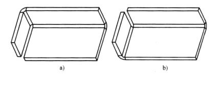
Even for bends with the same function, in the original design, the low bending strength is due to the attachment of the bend to the shorter side. In the improved design, by attaching the bend to the longer side, the bending strength is increased.
The greater the number of bending processes for the sheet metal part, the higher the mold cost and the lower the bending precision. To minimize these issues, the sheet metal design should aim to minimize the number of bending processes, as shown in the figure below.
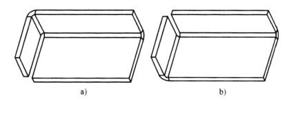
In the original design, the sheet metal required two separate bending processes. However, in the improved design, the sheet metal only needs one bending process to form the two sides at the same time.
It is important to keep in mind that the more complex the bending process for the sheet metal, the higher the amount of material waste that may result. To minimize this, it may be necessary to consider splitting a complex bend into two parts.
While this approach may go against the principle of reducing the number of parts, it can ultimately lead to lower production costs and improved product quality. It is important to verify these designs with thorough calculations.
As demonstrated in the figure below, the sheet metal part with complex bending is divided into two parts, which are then joined together using methods such as riveting, self-riveting, or spot welding.
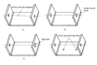
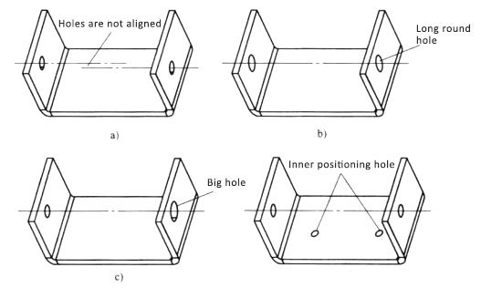
Many engineers likely have experienced the frustration of screws or nail holes on sheet metal bending being misaligned, making it impossible to fix screws or rivets. This is a common issue due to the large sheet metal bending tolerances, particularly when the sheet metal has multiple bends.
| Features | Tolerance/mm |
|---|---|
| One bend | 0.15 |
| Two bend | 0.25 |
| Three bend | 0.36 |
| Four bend | 0.44 |
| Five bend | 0.51 |
| Six bend | 0.59 |
As shown in the table above, the more times the sheet metal is bent, the greater the bending tolerance becomes. This makes it difficult to maintain the accuracy of the dimensions of the multiple bends in the sheet metal. This is why screw holes, pull holes, and self-rivet holes on sheet metal tend to be misaligned after bending.
Therefore, when designing a product, engineers must take into account the effects of multiple bending tolerances, avoiding overly strict tolerances on features with multiple bends in the parts.
At the same time, the sheet metal design should be optimized to avoid the following issues during assembly, such as misalignment of assembly holes, difficulty in maintaining the proper assembly size, and even assembly interference.
The solution for the holes on the two bends of the sheet metal is difficult to align due to the large bending tolerance:

As the founder of MachineMFG, I have dedicated over a decade of my career to the metalworking industry. My extensive experience has allowed me to become an expert in the fields of sheet metal fabrication, machining, mechanical engineering, and machine tools for metals. I am constantly thinking, reading, and writing about these subjects, constantly striving to stay at the forefront of my field. Let my knowledge and expertise be an asset to your business.