10 Essential Tips for Using a Grooving Tool
Ever wondered how to perfect the art of using a grooving tool? This article covers the 10 essential tips to optimize your grooving process, from selecting the right tool and…
Ever wondered how metal sheets achieve those precise, flawless bends? This article unveils the magic behind V-grooving machines. Learn how they transform metalworking, enhancing precision and aesthetics in industries from elevators to high-end decorations. Get ready to explore the fascinating world of V-groove bend forming and its revolutionary impact!
A groover, also known as a V groover or V grooving machine, is a tool used to scribe and slot V-shaped grooves into metal plates. This can reduce the bending radius and improve the appearance of sheet metal workpieces.
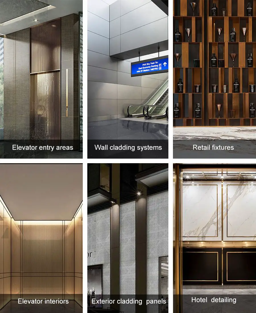
The machine is particularly useful in industries requiring high-precision plate processing, such as elevator manufacturing, packaging materials, stainless steel processing, household appliance production, and prop display.
With the development of the economy, places such as hotels, restaurants, shopping malls, banks, and airports have an increasing demand for metal decorative materials with bend forming in middle and high-grade decoration.
Traditional bending methods such as forced bending, free bending, and even three-point bending have been unable to meet the above requirements.
In other words, bending the metal sheet with a press brake alone cannot meet the design requirements of the designer and cannot achieve the grade and decorative effect of middle and high-grade decoration.
Therefore, a novel bending technique has been developed, which is V-groove bending technology.
What is the fabrication process of V-groove bend forming?
To put it simply, it is:
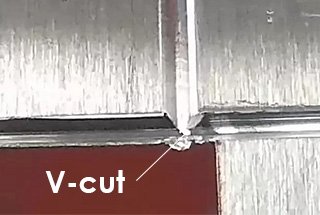
First, adopt the V-grooving (or V-cut) method on the metal sheet. Then, bend the grooved sheet metal into various angles and shapes using a press brake with a general mold or special mold.
Such a curved workpiece can meet the special needs of high-end decoration in hotels, restaurants, shopping malls, banks, and airports.
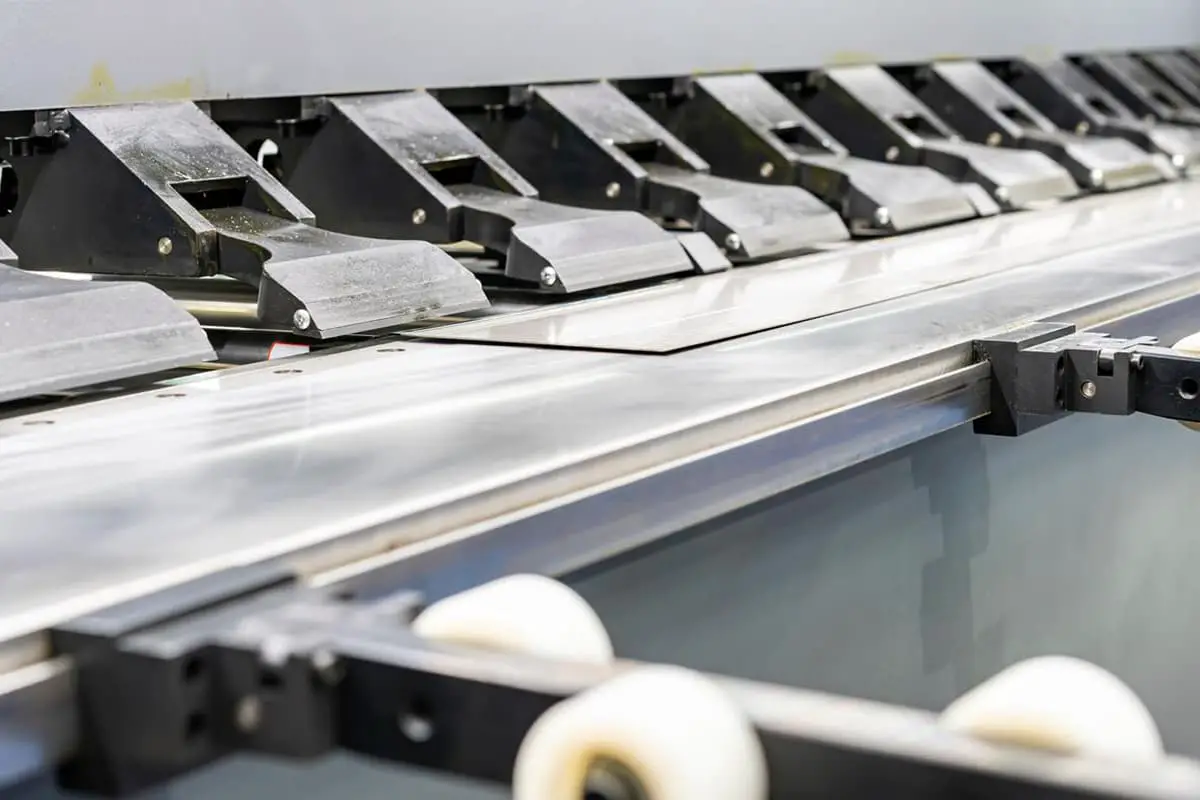
The main equipment of v-groove bending technology is press brake and sheet metal V-groover (also been called V-grooving machine).
The press brake is a traditional plate bending machine, and the thin plate V-grooving machine is a new type of sheet metal processing machinery, which is the key equipment of V-cut bending technology.
To better understand the press brake machine, you can refer to The Ultimate Guide to Press Brake.
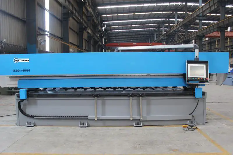
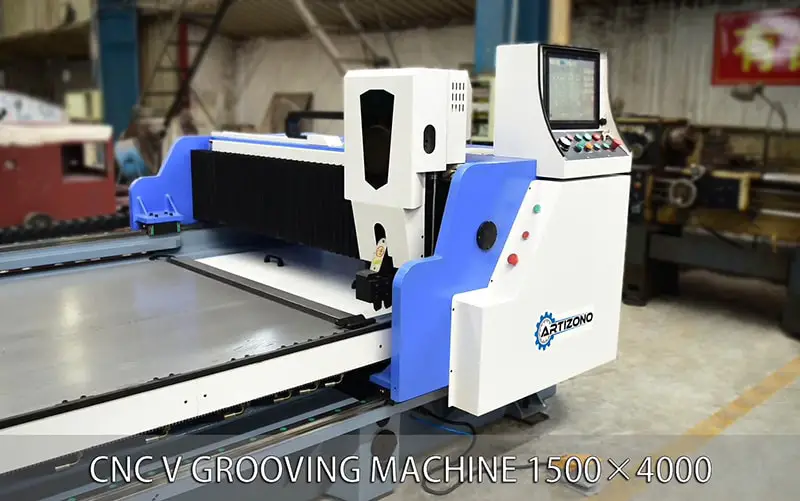
So, what is sheet metal V-grooving Machine?
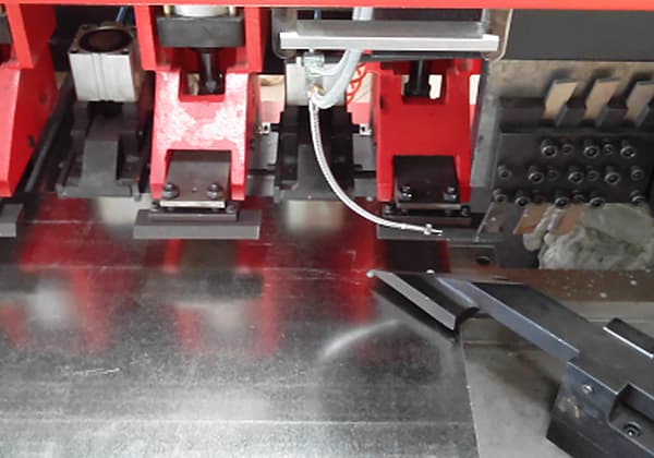
The V-groover is also known as the CNC V-Cutting Machine or V-grooving Machine. It is mainly used to achieve a certain depth of V-cutting on stainless steel plates, ordinary steel plates, aluminum plates, copper plates, and composite plates under 4mm before bend forming.
The workpiece produced with this technique has a small bending radius, no obvious color changes, and small bending force requirements. In addition, it reduces the straightness error of the round edge of narrow long workpieces, and the common press brake and toolings can be used to bend the workpiece with a complicated section shape.
V-grooving machines are widely used in industries such as stainless steel decoration, elevators, security doors, and cabinets.
Before the development of special V-grooving equipment, workshops generally used planers to make V-shaped grooves on metal sheet material. However, because the planer lacks an effective metal sheet pressing device, the V-grooving depth of the metal sheet and the positioning distance of the V groove cannot be precisely controlled. Additionally, planers have high energy consumption and low efficiency.
Currently, V-grooving for metal sheets is accomplished with a new type of metal sheet grooving machine designed and manufactured according to the special needs of the middle and high-end decoration industry and elevator manufacturing industry. This machine can make V-shaped grooves for materials such as stainless steel sheet, iron plate, and copper plate. With the installation of specially dedicated accessories, the metal sheet V-grooving machine can also be used for grinding, polishing, and drawing of metal sheet materials and profiles.
The basic principles of the metal sheet grooving process are as follows:
The metal plate is fixed, and the V-groover blade mechanically cuts the metal material on the movement track to form a V-groove.
The size of the bending angle is related to the depth of the V-groove.
The smaller the bending angle, the greater the value of the V-groove depth that needs to be grooved.

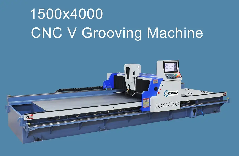
There are several technical parameters that have a greater impact on the grooving process.
The following uses the technical parameters of a grooving machine as an example (Figure 2).
Fig.2 Technical parameters of V grooving machine
| Model | 1250×4000 |
|---|---|
| Max Grooving Width (mm) | 1250 |
| Max Grooving Length (mm) | 4000 |
| Max Grooving Depth (mm) | 4 |
| Min Grooving Depth (mm) | 0.8 |
| V-groove minimum distance from side (mm) | 10 |
| Grooving Speed (m/min) | 40 |
| Resolution of tool carrier left-to-right movement (mm) | 0.001 |
| Positioning accuracy (mm) | ±0.001 |
| Resolution of tool carrier up-and-down movement (mm) | 0.001 |
| Positioning accuracy (mm) | ±0.01 |
| Main Power (Kw) | 4.4 |
(1) Maximum width and length of the slotted sheet: This parameter affects the maximum size of the sheet metal that the V-grooving equipment can process.
(2) Maximum thickness of the slotted sheet: This parameter affects the maximum thickness of the sheet metal that the equipment can process.
(3) The minimum distance of the V-shaped groove from the edge: This parameter reflects the minimum distance between the edge of the grooved sheet and the edge of the plate material when processing metal plates. This distance is mainly used for the grooving machine to grip the slot distance. Plus, the safety distance set by the manufacturer, the smaller the minimum distance value of the V-shaped slot from the edge, the smaller the minimum distance value of the slot edge from the plate material edge.
(4) Cutting speed: This parameter reflects the speed of the tool’s linear movement when processing metal plates. The larger the value, the higher the equipment processing efficiency.
(5) Left and right, up and down movement resolution, and positioning accuracy of the tool holder: Each parameter mainly reflects the processing accuracy of the equipment. At present, the minimum positioning accuracy that domestic technology can achieve is ±0.01mm.
In addition to the above-mentioned equipment parameters affecting the grooving process, another important parameter is the blade.

The quality and number of blades directly affect the machining efficiency and the speed of tool wear.
Traditional grooving equipment uses three blades for simultaneous cutting, and current technology uses four blades for simultaneous cutting.
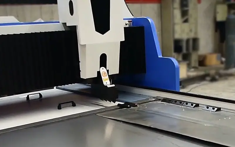
The structure of the blade is shown in Figure 3.
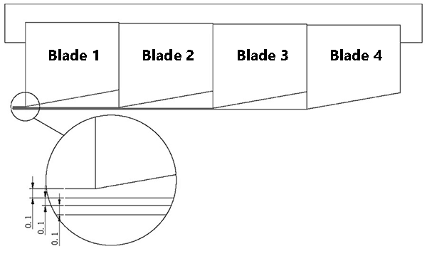
Figure 3 Schematic diagram of the tool structure
There is a distance of 0.1mm between each blade, and the maximum depth of a single groove with four blades can reach 0.6mm.
To ensure the quality of the grooving process and prolong the life of the blade, the depth of a single grooving process set by most companies is 0.4 to 0.5mm.
The latest blades developed in the industry are made of alloy, and each blade can be used to groove 2500 to 3000 meters of stainless steel material.
Currently, the length of the metal plate for V-grooving is: 2500mm, 3200mm, 4000mm, 5000mm, 6000mm and the processing width of sheet metal mainly is: 1250mm, 1500mm, 2200mm, 2400mm.
The most popular type is 4000×1250 (L*W) V grooving machine.
If classified by the structure style, the sheet metal V-grooving machine can be divided into 4 types:
The beam structure is fixed, and the tool holder can be positioned on the crossbeam before the groove.
The metal sheet to be processed is fixed on the worktable by a pressing device, and the V-shaped groove is made by moving the worktable back and forth along the long rail. This process is similar to a dedicated planer.
However, the energy consumption is very high during sheet metal V-grooving because the worktable, which is driven by the motor, moves back and forth along the long rail.
The worktable is fixed, and the processed sheet is fixed on the worktable by a pressing device. The tool holder is positioned on the crossbeam by moving left and right. The V-grooving is realized by the beam moving back and forth along the long rail on the worktable. During the V-grooving process, the worktable is fixed, but the energy consumption is very high due to the reciprocating motion of the beam along the long rail.
The worktable is fixed, and the sheet being processed is fixed on the worktable using a pressing device.
The beam moves back and forth along the short rail of the worktable to conduct pre-grooving positioning.
The tool holder conducts V cutting by moving left and right along the beam.
The energy consumption is low due to the fixed worktable and beam during V-grooving, and the power needed to drive the tool holder’s reciprocating motion along the long rail is much less than the power needed to drive the worktable and beam.
Fixed beam and worktable, and the processed sheet is positioned for pre-grooving by the feeding device moving back and forth.
The tool holder conducts the V-cutting with left and right reciprocating motion on the beam.
During V-cutting, it only drives the tool holder to do reciprocating motion along the long rail, and a light-duty feeding device is adopted for pre-grooving positioning without the need to drive a multi-ton beam.
Therefore, it has the lowest energy consumption and the most obvious energy-saving effect.
If classified by the control method, the thin plate V-groover can be divided into:
The display resolution is 0.01 mm, enough to meet the actual requirements.
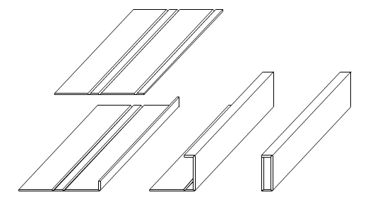
Fig.1 V-grooving bend forming process
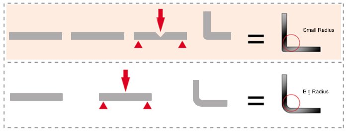
1. Small bending force requirement for bending the workpiece
It can be seen from the bending force calculation formula that the bending force required for the workpiece is proportional to its plate thickness.
The bending force is larger for bending thick plates and smaller for thin workpieces.
In V-groove bending technique, the bending force needed is reduced by V-cutting the plate at the bending position, effectively reducing the plate thickness.
As the depth of the V-shaped groove is half of the plate thickness, this can save up to 50% of the bending force.
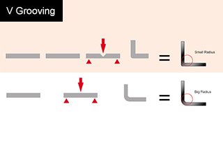
2. A small bending radius of the workpiece
For free bending, the bending radius is proportional to the V-opening width of the die. The width of the die opening is generally 8 to 12 times the thickness of the plate.
To obtain a smaller bending radius, you need to select a die with a smaller V-opening width.
The thicker the plate, the larger the V-opening width of the die, and the bigger the bending radius.
On the contrary, the thinner the plate, the smaller the V-opening width of the selected die, and the smaller the bending radius.
The thickness of the plate is reduced at the bend position by V-grooving, and the bending radius of the workpiece is naturally proportionally reduced.
In the plate strength range, the thinner the remaining thickness, the smaller the bending radius of the workpiece.
3. Small color changes at the bent round edges of the workpieces
During the V-shape bending process of the plate, the inside of the workpiece’s bending radius is under compressive force and undergoes compression deformation.
The outside of the bending radius is under tensile force and undergoes elongation.
The main factors that influence the color changes of the bent round edge of the workpiece are the elongation deformation caused by the lateral tensile strength.
It can be seen from the V-shape bending process of the sheet that the elongation deformation caused by the lateral tensile force is also related to the thickness of the plate.
By V-grooving the plate, the thickness of the plate at the bending position is reduced and the elongation deformation generated by the lateral tensile force during bending is also reduced, thus achieving the purpose of small color changes at the bent round edges of the workpiece.
4. Small straightness errors of the bent round edge of the narrow long workpiece
In the process of bending a narrow long workpiece, the inside of the bending radius generates compression deformation under compressive force in the width direction, while the deformation materials move at both ends in the length direction. The outside of the bending radius generates elongation under tensile strength in the width direction, with the materials moving towards the center in the length direction.
This results in the bent edge line of the workpiece forming a center-concave shape. The larger the bending deformation, the more severe the center-concave shape of the edge line. Conversely, the smaller the bending deformation, the less severe the center-concave shape of the edge line. Since V-grooving reduces the plate thickness at the bending position, the bending deformation is also reduced.
Therefore, the V-grooving bend forming technique minimizes the straightness errors of the edge line of the narrow long workpiece.
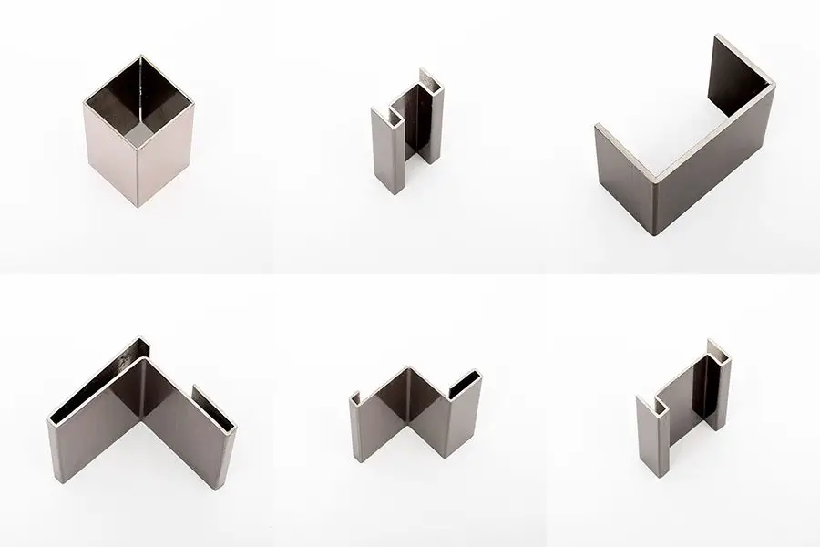
For press brake, only general toolings are needed to conduct the V-grooving bend forming technique.
Some workpieces with complicated or enclosed cross-sections can be bent without special toolings by correctly controlling the grooving depth and edge length (as shown in Fig. 2), which will reduce the expense incurred by complex toolings with special design and shorten the processing cycle.
Fig.2 Workpiece cross-section shape
Due to the obvious advantages of V-shaped groove bending technology, and the fact that the traditional bending method and equipment do not need to be changed, only the sheet metal V-grooving machine needs to be added, so V-grooving bend forming technology has been widely used in the emerging middle and high-grade decoration industry in the first place.
It was then adopted in elevator manufacturing.
Next, some experts in medical device manufacturing and electric control cabinet manufacturing industry also showed their interest in V-grooving bend forming technology.
It can be seen that with a deep understanding of the V-grooving bend forming technology, the application field of this technology will be broader.
Open the air switch on the right side of the electrical box and then turn on the key switch on the front panel.
The entire machine is powered on.
The touch screen will display the initial screen after a three-second delay.
On the light touchscreen, the whole machine enters operation monitoring, and it displays the following information:
(1) Beam position
This position represents the distance between the beam and the initial point, and it is detected by the screw encoder. The displayed numbers indicate the number of the grooving line.
(2) Target position
The target position of the current moving beam is displayed. If the grooving machine has not started grooving when the beam reaches the target position, press the “beam movement” button, and the machine will not move.
(3) Current distance
This distance is the distance between the current groove and the previous groove.
(4) Blade holder position
The blade holder position is displayed as a 3D point relative to the origin point or the initial point. The position is measured by the stepper motor encoder on the screw rod, and if the position is greater than 29.8mm, the tool holder will not move. The number at the back indicates the number of grooving.
(5) The plate width and plate thickness are set as working parameters.
(6) Press the start button to begin grooving when the position light flashes. When the depth light flashes, press the “Move” button to move to the next position for grooving.
(7) Press “manual operation” to manually control the operation screen.
(8) Press the “open groove preparation” button to move the beam to the front of the platform, and initialize the various grooving parameters to prepare for the grooving of the next metal plate.
The beam will not move if the beam position is less than the initial position offset, but the parameter initialization is normal, and the button should not be pressed during grooving.
(9) To replace the blade, a grooving pause button is set.
When the button is pressed, the grooving machine will stop working, and then press the button to restart the machine.
(10) Press “parameter setting” to jump to the parameter setting screen.
(1) “Beam forward” means moving the beam forward manually, and the moving speed is set in the system parameters.
(2) “Beam backward” means moving the beam back manually, and the moving speed is set in the system parameters.
(3) “Tool holder to the left” means moving the tool holder to the left manually, and the movement speed is set in the system parameters.
(4) “Tool holder to the right” means moving the tool holder to the right manually, and the moving speed is set in the system parameters.
(5) “Tool holder up” means moving the tool holder up manually.
(6) “Tool holder down” means moving the tool holder down manually.
(7) “Operation instructions”: press this button to move the screen to the operation instruction screen.
(8) “Origin alignment”: press this button to perform the function of returning the original to correct the position of the beam.
In general, there is no need to perform the function of returning to the origin (because the computer does not have the function of location memory).
However, if the grooving machine has stopped for more than two days, or if the position is not correct due to some other circumstances, the function of returning to the origin should be performed first after electrification to ensure the normal operation of the machine.
The system parameters have several types of buttons:
(1). “Deceleration advance” is the position where the beam decelerates from high speed to a constant speed.
This parameter is crucial for positioning.
If each positioning exceeds the stroke, then increase this parameter, generally set to 8mm, with a maximum setting of 9.999mm.
(2). “Positioning ahead” is the designated pre-stop positioning position.
After the stop, the beam moves to the positioning position under the action of inertia.
If the grooving machine doesn’t stop at the correct position for each stop, it means the parameter setting is too large.
Otherwise, the parameter setting is too small. The maximum data of this parameter can be set to 0.8mm.
(3). “Allowable error” is the allowable error after positioning. It is not allowed to groove if not in this range, and manual correction is required.
(4). “Initial point error” refers to the distance between the blade tip and the edge after correcting the origin.
The minimum setting is 8mm.
Otherwise, the front-positioning proximity switch needs to be adjusted in time.
1). Grooves must meet the following conditions
2). Moving beam
When finished with the grooving, press the “Move Beam” button to move the beam to the next grooving position, which is automatically added to the target position by the grooving machine.
After the beam automatically positions itself, a grooving process must be carried out before the beam can move again. This process continues until all the grooving lines have been completed.
3). Conditions for moving beams
4). Press the “Grooving ready” button to move the beam to the front of the platform.
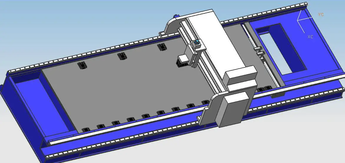
When deciding to purchase a V-grooving machine, you may face the dilemma of choosing between a gantry (horizontal) V-grooving machine and a vertical V-grooving machine. Let me explain the difference between the two.
Currently, there are two types of V-grooving machines on the market: vertical and horizontal.
The structure of the vertical V-groover is similar to that of the door frame type. The fixture is used to position the plate at the corresponding processing position. After clamping, the V-groove is processed by the cutter movement. The tool only performs linear movement of the processing, and the plate is moved to cooperate with the tool processing.
The principle of the horizontal V-groover is opposite to that of the vertical V-groover. It has a large working table, and the plate is fixed on the table by pressure clamps. The cutter is a gantry automatic mechanical structure. The tool moving device on the gantry first locates the machining route on the Y-axis, and then the gantry drives the tool to perform the V-groove machining on the X-axis. The plate is fixed and processed by the movement of the cutter.
Each type of groover has advantages and disadvantages (Table 1).
Table 1 Comparison of vertical and horizontal V groover technology
| Item | Vertical V Groover | Gantry V Groover |
|---|---|---|
| Processing range | When processing workpieces that need to be grooved around, if the workpiece is long, you need to add a table to carry the workpiece when processing the short side, which is inconvenient to operate. | Three-axis CNC machining with a large processing range, suitable for a variety of large-sized shapes. |
| Worktable processing technology | The worktable surface is made of high-quality mold steel after overall heat treatment, and is finely ground by a grinder. The surface fineness reaches a mirror effect. | The worktable surface is welded by ordinary iron plates. The hardness of the workpiece is higher than it. The grooving steel wire, damaged blades, etc. will make the worktable surface pitted (requires the self-planing function to restore the worktable surface regularly). |
| Processing efficiency | The minimum distance between the V-shaped groove and the edge is 10mm, and the cutting speed is 40m/min. | The minimum distance between the V-shaped groove and the edge is 8mm, and the cutting speed is 50m/min or higher. No need for reciprocating feeding, so is more efficient. |
| Power loss | The tool carrier moves back and forth with less loss (main motor power 4.4kW). | The gantry and the tool carrier are moving back and forth together, and the loss is large (the main motor power is 5.5kW). |
| Safety | The vertical grooving machine automatically clamps the workpiece by hydraulic pressure, automatically positions and works automatically. The operator is away from the moving parts of the machine. | The workpiece is clamped within the movement range of the machine. The gantry moves at high speed, and the control part runs with the gantry. The operator needs to pay attention to safe use. |
| Overall effect | Due to the need for automatic feeding after gripping the workpiece, the iron scraps generated by the grooving often scratch the decorative surface, and frequent alignment and movement are required when processing large-sized workpieces, which is more likely to damage the surface. | The workpiece does not need to be moved during processing. It can be operated by one person during the whole process, and the decorative surface of the workpiece will not be scratched, ensuring the surface processing quality (an important reason for use in the elevator industry). |
The application characteristics of the two can be seen from the comparison items.
The specific choice of equipment for processing needs to be determined according to industry requirements and workpiece characteristics.
Generally, the gantry V-grooving machine has high working efficiency, however, the accuracy of grooving (slotting) is not as good as the vertical V-grooving machine.
Furthermore, if the sheet metal is in a non-specific shape (cut by laser cutting), and more grooving lines will be needed, then we suggest you choose a vertical V-grooving machine.
If the sheet metal is a whole piece or a more symmetrical piece, such as square or rectangular, we recommend choosing the gantry or horizontal type V grooving machine.
In addition, the current price of the gantry type V grooving machine is slightly lower than the vertical V grooving machine, and the gantry type is still the more popular option and is selected by most customers.
As customers have higher and higher requirements for the aesthetics of their products, the application of the grooving process is becoming more and more widespread.
It is believed that the grooving process will definitely bring more benefits and contributions to the manufacturing industry in the future.

As the founder of MachineMFG, I have dedicated over a decade of my career to the metalworking industry. My extensive experience has allowed me to become an expert in the fields of sheet metal fabrication, machining, mechanical engineering, and machine tools for metals. I am constantly thinking, reading, and writing about these subjects, constantly striving to stay at the forefront of my field. Let my knowledge and expertise be an asset to your business.