Bend Allowance Formula: Calculator & Charts
Have you ever wondered how to precisely calculate the bending allowance for your metal fabrication projects? In this blog post, we'll explore the fascinating world of bend allowance formulas and…
Have you ever wondered how massive steel structures on locomotives achieve their precise curves? In this article, we reveal the secrets behind creating large bend radii in sheet metal parts. You’ll learn about innovative methods like bump bending and step bending, and how they transform flat metal sheets into complex, curved masterpieces. Get ready to uncover the engineering magic that makes these impressive structures possible!
Large arc workpieces are a common type of locomotive steel structure sheet metal products. Their structures are variable and the processing difficulty is greater than ordinary workpieces.
In this post, we introduce a process method to achieve a large bend radius in sheet metal parts and describe the method’s use in detail with a specific bent workpiece. The bump bending method can also be used to make a cone in a press brake.
In the practical production of workpieces with a large radius, there are generally three forming methods:
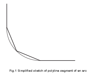
The basic principle of the multi-step forming process is to roughly divide the arc segment into polyline segments, as shown in Figure 1, to achieve the purpose of bending sheet metal with a large radius using a small radius punch.
Compared with the arc segment, the forming effect of the polyline segment is positively related to the number of polyline segments.
With this process method, it is difficult to avoid a prismatic structure on the surface of the workpiece. However, for non-exposed workpieces, considering the production cycle and cost comprehensively, this process method can be used.
How to determine the polyline segmentation and bending angle of circular arc segments:
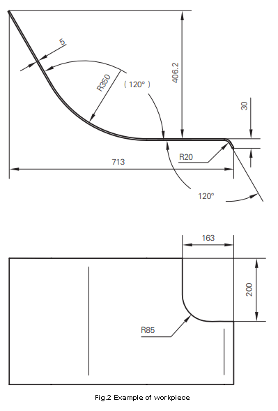
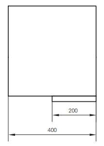
As shown in Figure 2, the inner radius of the bending arc of this workpiece is R350, the bending angle is 120°, and the plate thickness is 5mm.
Since the use environment of the workpiece satisfies the conditions of the bump bending method mentioned above, the multi-step bend forming method is used for processing.
Based on past experience and the existing mold conditions in the workshop, the upper mold adopts a R120 radius punch.
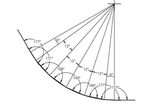
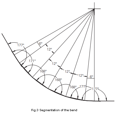
After analyzing the large arc segment of the workpiece in Figure 2, this R350 arc segment is divided into 6 polyline segments.
It should be noted that, to ensure the smooth transition of the arc segment and the straight segment of the workpiece (i.e., the two ends of the arc segment), the segmentation angle should be set to half of the other segments where the arc segment is tangent to the straight segment.
According to FIG. 3, it can be seen that the workpiece in FIG. 2 is formed by bending 7 times.
When the electro-hydraulic servo press brake machine bends sheet metal parts, three basic parameters are required: the thickness of the sheet, the bending angle, and the position of the bending line.
The first and second split angles are calculated as 6°, and the others are 12°. The bending angle after the split can be directly measured by CAD software. The specific bending angle is shown in Figure 3.
Bending line position size and unfolded size confirmation
To ensure the accuracy of the unfolded dimensions of the bend line, there are generally two methods: the neutral layer expansion calculation method and the software-assisted expansion method.
To obtain the bending data concisely, quickly, and accurately, the software-assisted expansion method is used for calculation.
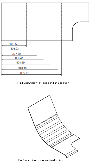
The divided part cross-section is directly imported into Catia, and the software’s Generative Sheet Metal Design module is used to generate the workpiece model. Then, the bend line and unfolded view are exported, as shown in Figure 4. The axonometric drawing of the workpiece is shown in Figure 5.
During production, it was found that some workpieces with small thickness (about 2mm) have serious deformation during processing, leading to a significant drop in processing accuracy and failure to meet design requirements. The reason for this is due to insufficient stress release in the sheet.
During laser cutting and blanking, we observed that the workpiece in this batch warped due to internal stress. This also provides a preliminary method to judge whether thin sheet metal with a large radius can be directly bent using the multi-bend process, that is, by observing the workpiece’s deformation during laser cutting.
If the deformation is serious, measures must be taken to release the internal stress, otherwise obtaining a qualified workpiece is difficult. If the production cycle allows, natural aging is an economical and effective method. However, the separated workpieces undergo aging treatment for a long time, which will inevitably produce floating rust on the surface. Therefore, they must be wiped or shot blasted with a rust remover, which increases labor and equipment costs.
Therefore, the direct use of steel plates that have undergone sufficient natural aging is the best choice. If the production cycle is not allowed, after the sheet is separated, annealing can also be used to eliminate internal stress, but the material’s hardness is reduced after annealing. Therefore, it is necessary to consider comprehensively whether annealing is performed according to the workpiece’s design requirements.
Calculation of workpiece expansion diagram in bump bending
It must be noted that when using the multi-step bending method to process sheet metal with a large radius, the actual workpiece conditions must be followed.
That is, the expanded view is calculated using the arc segment after approximating the polyline segment. The expanded view of the workpiece calculated according to the arc cannot be directly used; otherwise, the workpiece will inevitably be out of tolerance after processing.
Shape detection of workpiece using multi-step bending process
It is worth noting that when using a general comparison match sheet to detect the arc size of a workpiece processed by bump bending, the match sheet must be designed as an outer seizing type, and the outside of the workpiece arc should be used as the detection surface.
If the comparison match sheet is designed with the inner side as the detection surface, and the match sheet interferes with the polyline segment, it will inevitably lead to the match sheet not being in place, resulting in detection failure.
As an ingenious process method, large arc bump bending has its characteristics of flexibility and efficiency but also has its limitations.
Specific problems must be analyzed in accordance with the design requirements and application of the workpiece.
It is necessary to comprehensively consider the production cost and the appearance quality of the workpiece to select the processing method.

As the founder of MachineMFG, I have dedicated over a decade of my career to the metalworking industry. My extensive experience has allowed me to become an expert in the fields of sheet metal fabrication, machining, mechanical engineering, and machine tools for metals. I am constantly thinking, reading, and writing about these subjects, constantly striving to stay at the forefront of my field. Let my knowledge and expertise be an asset to your business.