Press Brake Operation Manual (Training PDF)
Attention all mechanics and engineering enthusiasts! Have you ever wondered about the ins and outs of operating a press brake machine? In this blog post, we'll dive into the world…
Imagine a machine that shapes metal with precision and efficiency, transforming raw sheets into intricate components. This article explores the press brake, a vital tool in metalworking, and reveals how its hydraulic system ensures flawless bending. Learn how this technology enhances product quality and boosts manufacturing productivity.
Press brake is a widely utilized bending machine that has achieved hydraulic efficiency. As a critical piece of equipment for sheet metal processing, it is irreplaceable and plays a decisive role in determining product quality, processing efficiency, and precision.
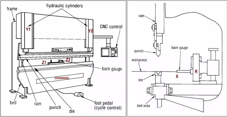
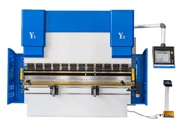
Typically, the press brake is an upper piston-style press machine comprised of several components, including a frame, sliding block, hydraulic system, front-loading rack, back gauge, mold, and electrical system, as depicted in Figure 1.
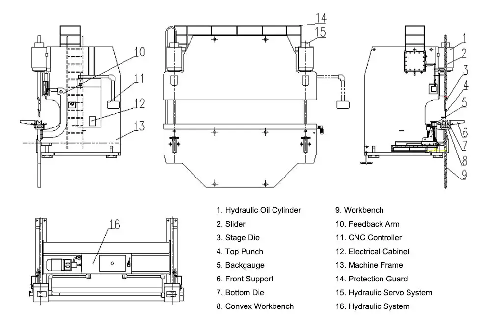
The hydraulic system of a press brake operates by forming vertical downward pressure through the use of two parallel working hydraulic cylinders. This pressure drives the die on the bending beam, allowing for the completion of the bending process.
The hydraulic control system, which acts as the “brain” of the press brake, is responsible for controlling the synchronized operation of the bending process and the positioning of the hydraulic cylinders during full loading of the press brake machine.
In this article, we will explore the workings of the press brake hydraulic system.
For each bending motion, the typical bending process of the upper bending beam includes:
The motor rotates in the direction indicated by the pump arrow, which is the clockwise direction, driving the axial piston pump. The oil is then discharged through the pipeline and into the valve plate and electromagnetic overflow valve before returning to the tank. When valve number 19 is closed, the oil in the lower cavity of cylinder number 20 is held in a fixed position.

The fast descending motion of the press brake is generated by the bending beam, the self-weight of the accessories, and the pressure of the oil. During this process, the hydraulic cylinder does not have a rod cavity through the filling valve, and any back pressure produced by the rod cavity causes the oil liquid to return quickly.
The fast forward movement starts from the top dead center and, after a brief period of deceleration, the ram slows down at a specific distance from the bending plate. The descending speed of the ram is adjusted by valve number 18, and the rapid drop is initiated by the operation of the electromagnets No. 9 YV1, No. 24 YV6, No. 13 YV4, and No. 17 YV5.
The oil in the lower chamber of cylinder number 20 enters the tank through valves 19, 18, and 17, while the upper chamber oil of the same cylinder is injected through valve 21. When the ram reaches the limit switch, electromagnets No. 9 YV1, No. 8 YV2, No. 11 YV3, No. 13 YV4, and No. 24 YV6 start working, causing the ram to transition to its working speed.
If the ram is out of sync, valve number 15 will automatically correct it. The drop position of the sliding block is restricted by the mechanical block within the cylinder.

The bending phase begins with the pressure buildup of the non-bar cavity.
The bending speed is limited by the quantity of oil supplied by the oil pump. On the other hand, it can be adjusted by the direction valve of the proportional valve.
At the same time, the direction valve also controls the synchronous operation of the bending beam and the positioning of the lower dead center.
The bending force is limited by the proportional relief valve to limit the pressure of the pump.
The corresponding values of speed, synchronization, positioning and pressure are all from the CNC.
The pedal switch or button controls the electromagnet working time, which includes No.9 YV1, No.8 YV2, No.11 YV3, No.13 YV4 and No.24 YV6, which realize the joggle distance when the sliding block drop.
The speed of slide drop is adjusted by valve 16.
The ram is controlled up by No.11 YV3 and No.24 YV6.
The length of the working time of the same electromagnet can realize the moving distance of the ram.
The stress relief of the no-bar cavity begins when it reaches the bottom of the dead center, or after a brief holding time, allowing the material sufficient time to form and enhancing the dimensional precision of the parts. The pressure holding and pressure relief are performed by the proportional directional valve, which is controlled by the numerical control device.
In an effort to improve processing efficiency, the time required for pressure relief should be minimized. However, to avoid unloading impact on the entire system, it is necessary to extend the discharge time as much as possible. In other words, the pressure relief curve should be as smooth as possible, avoiding steep drops.
The optimization of the entire process is achieved through the use of the proportional directional valve.

The pump flow and the hydraulic cylinder have a pressure area in the bar cavity, which determines the maximum return speed, which is typically close to the fastest speed. The return process requires synchronous operation, starting with the pressure reduction of the bar cavity and ending at the upper dead center.
At the moment of return, it is necessary to reset the pressure of the No. 8 YV2 electromagnet for 2 seconds, then the electromagnets No. 11 YV3 and No. 24 YV6 start working and the sliding block begins to return at a constant speed.
Valve No. 6 and No. 11, the high-pressure overflow valve and electromagnetic overflow valve, respectively, are primarily responsible for maintaining the rated power of the press brake. Meanwhile, valve No. 14 regulates the return force of the machine to prevent damage caused by overload.
The pressure within the hydraulic system can be monitored via the pressure gauge No. 7. The nitrogen pressure in accumulator No. 10 mainly controls the pressure necessary for the operation of valves No. 19 and No. 21.
Each stroke of the press brake machine is divided into three working conditions, namely:
There are three specific points that determine the starting and ending positions of each working condition, namely:
Correspondingly, the ram moves at three speeds, namely:
In a press brake machine cycle, from the top dead center to the speed change point, the ram moves downward rapidly at no-load speed.
From the speed change point to the bottom dead center, the ram moves downward at the working speed, and the bending of the workpiece is completed during this phase.
From the bottom dead center to the top dead center, the ram moves upward at the return speed, completing one cycle of the machine.
The three speeds and the positions of the three specific points can be adjusted through the numerical control system.
For an Electro-Hydraulic Synchronous CNC Press Brake Machine, there is a particular point known as the clamping point, which corresponds to the upper surface of the sheet on the lower die. The workpiece will be bent from this point, which is calculated automatically by the numerical control system.
The hydraulic transmission medium used is hydraulic oil, and its quality directly affects the performance and lifespan of the machine. In particular, the Electro-Hydraulic Synchronous CNC Press Brake Machine is equipped with a proportional servo valve, making the requirements for the hydraulic oil more stringent compared to other bending machines.
Users are advised to filter the hydraulic oil at least once a year.
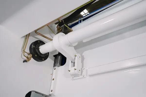
The Torsion Shaft Forced Synchronization Control Technology is used in the operation of the ram of a bending machine.
The synchronous shaft is located on the left and right panels of the frame body and is connected to the ram through a connecting rod.
During operation, if one end of the ram moves faster, the ram drives the swing arm of the synchronous shaft to twist it through the connecting rod. The rigidity of the synchronous shaft generates a reverse force that reduces the speed of the ram, ensuring that the rams (Y1, Y2) run synchronously and maintain a parallel state to the worktable.
The precise positioning of the ram is achieved through the Rigid Positioning Control Technology of the built-in mechanical block. There are mechanical stops in the left and right oil cylinders, which stop the downward movement of the piston rod after it contacts the locating surface of the mechanical stop, controlling the final stroke position of the oil cylinder.
The mechanical stops of the left and right oil cylinders are adjusted synchronously through the connecting rod to control the relative parallel state of the rams (Y1, Y2) to the worktable.
The Press Brake Machine uses two oil cylinders to drive the ram up and down, completing the bending process. The synchronization of the two cylinders and the accurate positioning of the bottom dead center are critical.
The Electro-Hydraulic Servo CNC Press Brake Machine precisely controls the synchronization of the two oil cylinders and the accurate positioning of the bottom dead center through the CNC system. This results in a smooth movement of the ram and accurate positioning at the bottom dead center.
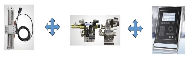
The position of the ram is detected in real-time by grating rulers installed on both sides of the machine and fed back to the CNC system. The numerical control system compares the feedback data from the two grating rulers and adjusts the proportional servo valve in the synchronous valve groups, controlling the opening size of the valve and the oil intake of the oil cylinder to keep the operation of the ram within an acceptable error range. This ensures that the rams (Y1, Y2) run synchronously and maintain a parallel state to the worktable.
The numerical control system also compares the feedback data from the grating ruler with the bottom dead center set by the system to confirm that the bottom dead center has been reached.
The Press Brake Machine uses a full closed-loop electro-hydraulic servo control technology for its synchronous control, with the position signal of the ram fed back to the numerical control system by the grating rulers on both sides. The numerical control system then controls the opening size of the synchronous valve and adjusts the oil intake of the oil cylinder, ensuring that the rams (Y1, Y2) run synchronously and maintain a parallel state to the worktable.

Synchronous schematic diagram of electro hydraulic synchronous CNC hydraulic press brake machine
If there is any positioning error on both sides of the ram, the numerical control system will send correction instructions to the two synchronous valves to maintain the parallel state of the ram to the worktable.
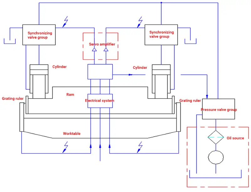
The diagram depicts the components of the synchronous system of the Press Brake Machine, which mainly consists of hydraulic oil control and electrical signal transmission.
The pressure oil is controlled by the two synchronous valve groups and enters the two oil cylinders to drive the synchronized movement of the ram. The position of the ram movement is detected in real-time by grating rulers on both sides and fed back to the CNC system.
The CNC system analyzes and calculates the data, controlling the two synchronous valve groups through the servo amplifier. The feedback signal of the proportional servo valve’s spool position is also received and analyzed, forming a dynamic closed-loop control.
Throughout the ram’s movement, the numerical control system sets the parameters according to the program, utilizing the grating ruler and the feedback signal from the proportional servo valve’s spool position to dynamically control the synchronous valve group and achieve synchronized operation and accurate positioning of the bottom dead center.
Therefore, the synchronous control system of the Electro-Hydraulic Synchronous CNC Press Brake Machine mainly consists of the CNC system, grating ruler, and proportional valve.
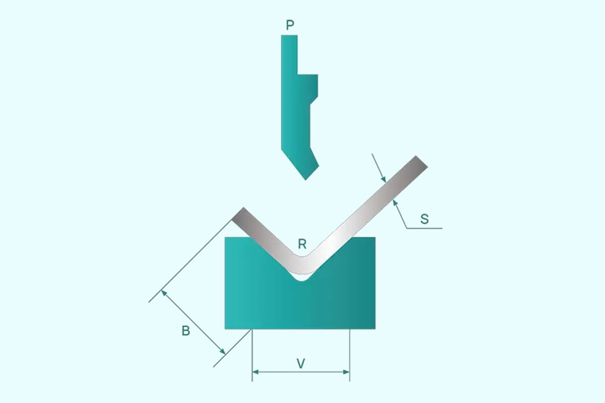
As shown above, the bending principle of the Electro-Hydraulic Synchronous Press Brake Machine is similar to that of a regular Press Brake Machine, which controls the bending angle by adjusting the pressing depth of the sheet in the lower die mouth through the top punch, or by pressing the workpiece into the same angle as the die.
The only difference is the control mode of the ram, which is controlled by the numerical control system through the electro-hydraulic proportional valve and the feedback from the grating ruler. This forms a full closed-loop, digital control mode for the bending depth.
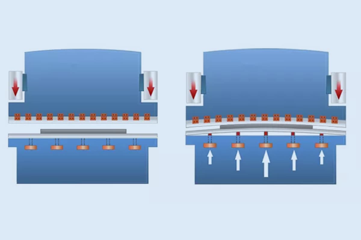
The difference between two kinds of synchronous mode of press brake machine
The standard press brake machine relies on the torque tube to ensure that the ram moves in synchrony, while the synchronization of the electro-hydraulic press brake machine is achieved through the balance in the hydraulic oil circuit.
It is worth noting that the torsion shaft press brake operates using open-loop control, whereas the electro-hydraulic press brake uses closed-loop control.
Electro hydraulic synchronous press brake machine has the following obvious advantages
The fully closed-loop control system in the electro-hydraulic press brake machine enables continuous monitoring and control of the cylinder’s stroke. Once the cylinder begins to tilt, the system promptly issues commands based on the readings from the scales located on either side of the cylinder, which then prompt the proportional valves to make adjustments to keep the cylinders in sync.
In the electro-hydraulic press brake machine, it is possible to have one cylinder working at full load while the other operates at zero pressure in an off-load pressurized state.
Additionally, the electro-hydraulic synchronization system allows the ram to be tilted at varying angles, making it possible to bend workpieces at different angles, which is not possible with traditional press brake machines.
The pressure in the electro-hydraulic synchronous system is automatically regulated in each operating condition by the proportional pressure valve based on the system parameters.
This system can also smoothly transition from fast to slow speed, reduce hydraulic impact, and improve system stability.
The precise control of the cylinder position in the electro-hydraulic press brake machine makes it possible to bend the same die at different angles, making it a highly flexible machine tool.
Moreover, the automatic control of the entire process reduces errors caused by human factors and each working condition can be adjusted and corrected through CNC parameters.
In conclusion, the electro-hydraulic press brake machine improves production efficiency, increases the accuracy of parts, and transforms the machine into a tool that works for the operator.

As the founder of MachineMFG, I have dedicated over a decade of my career to the metalworking industry. My extensive experience has allowed me to become an expert in the fields of sheet metal fabrication, machining, mechanical engineering, and machine tools for metals. I am constantly thinking, reading, and writing about these subjects, constantly striving to stay at the forefront of my field. Let my knowledge and expertise be an asset to your business.