Hydraulic Press Brake Maintenance Checklist
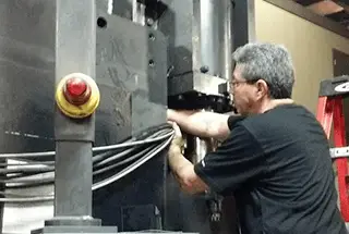
Is your hydraulic press brake causing more headaches than it should? Ensuring these complex machines run smoothly is vital to avoid costly downtime and repairs. This article covers essential maintenance…
The hydraulic control technology of hydraulic press brakes has undergone three distinct stages of control: pressure proportional control, flow servo proportional control, and electro-hydraulic hybrid control technology. This development represents a progression from basic control to precise control, ultimately resulting in the ability to simultaneously save energy and reduce usage costs. With the implementation of […]
The hydraulic control technology of hydraulic press brakes has undergone three distinct stages of control: pressure proportional control, flow servo proportional control, and electro-hydraulic hybrid control technology.
This development represents a progression from basic control to precise control, ultimately resulting in the ability to simultaneously save energy and reduce usage costs.
With the implementation of electro-hydraulic hybrid technology in hydraulic bending machines, there has been a significant shift from coarse to refined technology.
When electro-hydraulic hybrid technology was first introduced, it was heavily influenced by superior CNC systems and technical knowledge. However, it simply replaced the asynchronous motor with a servomotor and utilized a multi-stage speed control method that estimated the hydraulic flow demand for each executive step in the bending cycle.
Due to this estimation, the oil pump driven by the servomotor must produce more flow than necessary. The excess flow is then forced to overflow through the relief valve, resulting in energy loss. Additionally, this control method is unstable and cannot adapt to the requirements of various processing techniques. The ram speed control is inflexible, and manufacturing costs are high.
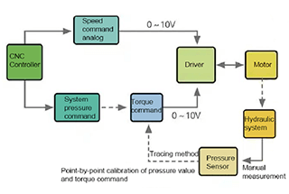
Fortunately, with the advancement of electro-hydraulic pump control technology and the accumulation of experience in multiple industries, the hydraulic press brake has been optimized further with a torque limiting control scheme, as depicted in Figure 1.

Figure 1 Framework diagram of torque limiting control scheme
This control scheme can solve not only the basic overflow situation but also further reduce the pressure proportional valve, which can save some hydraulic system costs.
Currently, this program is mainly used to support the hydraulic flow analog command of the NC system. However, there are still some CNC systems in the market that do not support dual analog work (hydraulic flow and hydraulic pressure) and can only use a combination of switching to form a multi-stage speed of the flow control with pressure analog command.
In addition to this apparent shortcoming, the torque limiting control scheme has another important limitation.
Before we delve into that, let’s briefly describe the working principle of the torque limiting control on a hydraulic press brake machine, as shown in Figure 2.
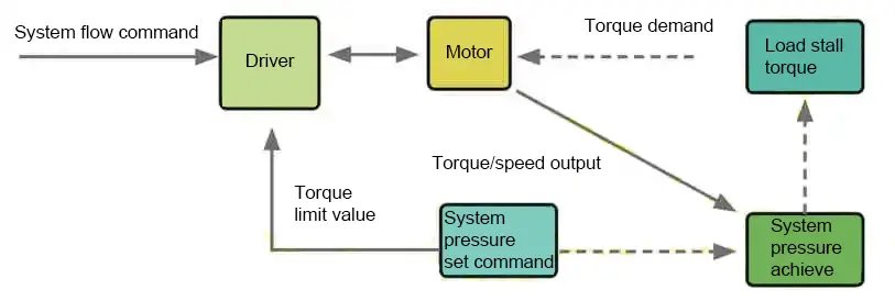
Figure 2 Correspondence between pressure and torque
The motor output torque is controlled by mapping the system pressure, which is achieved through a basic PID control system. While the principle is simple and easy to understand, a non-linear relationship exists between the pressure command, the torque limit value, and the actual pressure value during specific implementation.
To correct this issue, the CNC system requires plotting points. The pressure accuracy requirement determines the number of tracepoints needed, and the corresponding adjustment man-hours will also increase accordingly. If tracepoints are reduced, the pressure deviation will increase.
In light of the above practical application defects, we propose corresponding solutions.
Add a pressure sensor to the control system to provide real-time feedback of the system pressure.
The advantage of this is that it completely eliminates overflow, allowing the system to meet the real-time flow demand of the process more accurately.
The pressure sensor outputs only the amount required and can maintain pressure accuracy within 0.1 MPa, significantly reducing adjustment time, as demonstrated in Figure 3.

Figure 3 Framework diagram of full closed loop pressure control mode
In response to the prevalence of CNC systems for press brake machines that only support flow switching commands in the market, our team has optimized the control firmware of the hybrid servo drive. This optimization enables the press brake machine to adopt a numerical control system that allows for more precise pressure control, without overflow.
As a result, our solution aims to improve accuracy, reduce energy consumption, and lower costs for our customers.
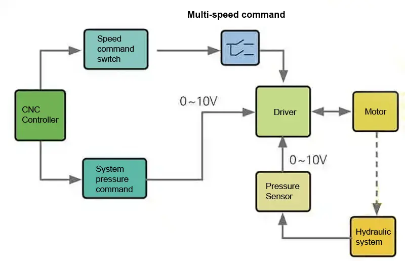
Figure 4 Framework diagram of the multistage flow control
The specific configuration and technical requirements of the plan are presented in Table 1.
Table 1 Configuration and technical requirements
| NO. | Name | Number | Technique requirements |
| 1 | CNC system | 1 | |
| 2 | Oil-electric servo motor | 1 | Maximum system pressure 30MPa |
| 3 | Oil-electric servo driver | 1 | Maximum motor speed 2000rpm |
| 4 | Rear damper servo driver | 1 | Ram fast down speed 150mm/s |
| 5 | Rear damper servo motor | 1 | Ram slow down speed 10mm/s |
| 6 | Pressure Sensor | 1 | Ram fast up speed 120mm/s |
| 7 | Inner gear oil pump | 1 |
As shown in Figure 5, during the actual bending process, the pressure output and the demand setting align closely in the pressure holding state. Furthermore, the output flow will automatically adjust according to the actual process.
Among them:

Figure 5 Full closed loop pressure control mode
As shown in Figure 6, the same control effect successfully addresses the issue of overflow in various processes within the simple multistage speed control scheme. This solution ensures the accuracy of pressure control and provides significant economic benefits.

Figure 6 Multistage flow pressure control mode
Among them:
In comparison to the commonly utilized electro-hydraulic control technology, our company’s hydraulic press brake pump control technique offers a superior control mechanism. It can meet the requirements of no overflow, oil temperature reduction, noise reduction, and accuracy improvement simultaneously without significantly increasing costs.
Furthermore, this technique can reduce costs and increase benefits for press brake manufacturers and end-users, making it an ideal solution to replace the electro-hydraulic control technology of hydraulic press brake.

As the founder of MachineMFG, I have dedicated over a decade of my career to the metalworking industry. My extensive experience has allowed me to become an expert in the fields of sheet metal fabrication, machining, mechanical engineering, and machine tools for metals. I am constantly thinking, reading, and writing about these subjects, constantly striving to stay at the forefront of my field. Let my knowledge and expertise be an asset to your business.