Sheet Metal Joining Process: The Ultimate Guide
Have you ever wondered how sheet metal parts are joined together to create complex structures? In this blog post, we'll explore the fascinating world of sheet metal joining techniques. As…
Have you ever wondered how to improve the efficiency and quality of your sheet metal projects? In this article, we delve into essential tips for sheet metal design, exploring techniques to minimize errors and optimize processes. From blanking to bending, each step is crucial for achieving precise, cost-effective results. By the end of this read, you’ll gain practical insights and strategies to enhance your sheet metal fabrication, ensuring both functionality and durability in your designs.

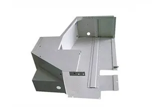
Sheet metal parts are commonly utilized in both the external surface coverings and internal structural components of automobiles.
As a control structural engineer, cost reduction is always a pressure I must bear in my main business.
After conducting extensive research, I discovered that my peers have successfully converted the controller’s upper cover into a sheet metal stamped part.
To avoid errors in the design process, I have gathered data and compiled a list of the common techniques in sheet metal part design. I hope to share and learn from others in the industry through this information.
Sheet metal processing involves four key processes: Blanking, Bending, Stretching, and Forming.
Each process has specific design requirements, and in this section, we will provide a brief overview of each process from four different perspectives.
Blanking is further divided into two categories: Ordinary Blanking and Precision Blanking.
As the processing methods differ, the technology used in the blanking process also varies.
The upper cover of the motor controller and other structural components typically only utilize ordinary blanking.
In this section, we will focus on the structure and technology of ordinary blanking that we commonly use.
It is ideal for the shape and size of blanking parts to be simple and symmetrical, as this minimizes waste during the layout process.
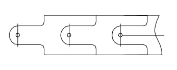
Layout of blanking parts
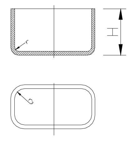
The shape and inner holes of blanking parts should avoid sharp corners.
Where straight lines or curves meet, an arc connection should be incorporated with a radius of R ≥ 0.5t, where t is the material’s wall thickness.
Minimum value of fillet radius of blanking part
Blanking parts with narrow cantilevers and slots should avoid deep and wide convex or concave sections.
As a general rule, these sections should not be less than 1.5t, where t is the material thickness.
Additionally, narrow and long notches, as well as excessively narrow notches, should be avoided to enhance the strength of the corresponding parts of the die.
Avoid narrow cantilevers and grooves.
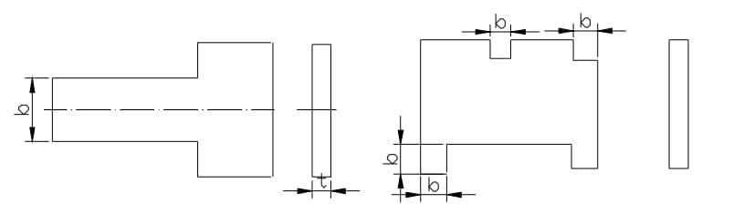
Circular holes are the preferred choice for punching, especially when considering minimum size requirements.
The minimum size for punching depends on factors such as the shape of the hole, the mechanical properties of the material, and the material’s thickness.
Punch shape example
| Material | Diameter of circular hole (b) | Width b of short side of rectangular hole |
| High-carbon steel | 1.3t | 1.0t |
| Low carbon steel, brass | 1.0t | 0.7t |
| Aluminium | 0.8t | 0.5t |
*t is the material thickness, and the minimum size of punching is generally not less than 0.3mm
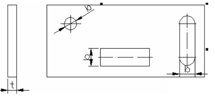
Punching hole spacing and hole edge spacing are important considerations.
The minimum distance between the punching edge of a part and its shape is limited based on the shape of the part and hole, as depicted in the accompanying figure.
When the punching edge is not parallel to the edge of the part outline, the minimum distance should not be less than the material thickness (t). When parallel, it should not be less than 1.5t.
Schematic diagram of hole edge distance and hole spacing of blanking parts
When punching bending and drawing parts, a certain distance should be maintained between the hole wall and the straight wall.
Distance between the hole wall of the bending part and the stretching part and the straight wall of the workpiece
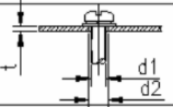
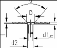
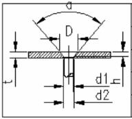
For through holes and countersunk seats for screws and bolts, the structural dimensions of the screw or bolt through hole and countersunk head seat can be found in the accompanying table.
When designing a countersunk head seat for a countersunk head screw, if the plate is too thin to accommodate both the through hole (d2) and the countersunk hole (D), priority should be given to ensuring the through hole (d2).
 | d1 | M2 | M2.5 | M3 | M4 | M5 | M6 | M8 | M10 |
| d2 | Φ2.2 | Φ2.8 | Φ3.5 | Φ4.5 | Φ5.5 | Φ6.5 | Φ9.0 | Φ11 |
Through holes for screws and bolts
 | d1 | M2 | M2.5 | M3 | M4 | M5 |
| d2 | Φ2.2 | Φ2.8 | Φ3.5 | Φ4.5 | Φ5.5 | |
| D | Φ4.0 | Φ5.5 | Φ6.5 | Φ9.0 | Φ10. | |
| h | 1.2 | 1.5 | 1.65 | 2.7 | 2.7 | |
| a | 90° | |||||
*It is required that the sheet metal thickness t ≥ h.
Countersunk head seat and through hole for countersunk head screws
 | d1 | Φ2 | Φ2.5 | Φ3 | Φ4 | Φ5 |
| d2 | Φ2.1 | Φ2.6 | Φ3.1 | Φ4.1 | Φ5.1 | |
| D | Φ4.1 | Φ5 | Φ5.5 | Φ7.2 | Φ9 | |
| h | 1 | 1.1 | 1.2 | 1.6 | 2 | |
| a | 90° | |||||
*It is required that the sheet metal thickness t ≥ h.
Countersunk seat and through hole for countersunk rivet
Blanking parts with excessive burrs that exceed a certain height are not permitted. The accompanying table shows the limit value (mm) for the burr height of the stamped part.
| Material wall thickness | Material tensile strength (N / mm2) | |||||||||||
| >100~250 | >250~400 | >400~630 | >630 | |||||||||
| f | m | g | f | m | g | f | m | g | f | m | g | |
| >0.7~1.0 | 0.12 | 0.17 | 0.23 | 0.09 | 0.13 | 0.17 | 0.05 | 0.07 | 0.1 | 0.03 | 0.04 | 0.05 |
| >1.0~1.6 | 0.17 | 0.25 | 0.34 | 0.12 | 0.18 | 0.24 | 0.07 | 0.11 | 0.15 | 0.04 | 0.06 | 0.08 |
| >1.6~2.5 | 0.25 | 0.37 | 0.5 | 0.18 | 0.26 | 0.35 | 0.11 | 0.16 | 0.22 | 0.06 | 0.09 | 0.12 |
| >2.5~4.0 | 0.36 | 0.54 | 0.72 | 0.25 | 0.37 | 0.5 | 0.2 | 0.3 | 0.4 | 0.09 | 0.13 | 0.18 |
*Grade f (precision grade) is applicable to parts with higher requirements;
m level (medium level) is applicable to parts with medium requirements;
Grade g (roughness) is applicable to parts with general requirements.
The minimum bending radius of bending parts: When a material is bent, the outer layer experiences stretching while the inner layer undergoes compression in the fillet area.
When the material thickness is constant, the smaller the internal radius (R), the more severe the material’s tension and compression become.
If the tensile stress in the outer fillet exceeds the material’s ultimate strength, cracks and fractures will occur.
Therefore, the structural design of bending parts should avoid excessively small bending fillet radii.
The minimum bending radius for common materials used by the company can be found in the accompanying table.
| Serial number: | Material | Minimum bending radius |
| 1 | 08, 08F, 10, 10F, DX2, SPCC, E1-T52, 0Cr18Ni9, 1Cr18Ni9, 1Cr18Ni9Ti, 1100-H24, T2 | 0.4t |
| 2 | 15, 20, Q235, Q235A, 15F | 0.5t |
| 3 | 25, 30, Q255 | 0.6t |
| 4 | 1Cr13, H62 (M, Y, Y2, cold rolling) | 0.8t |
| 5 | 45, 50 | 1.0t |
| 6 | 55, 60 | 1.5t |
| 7 | 65Mn, 60SiMn, 1Cr17Ni7, 1Cr17Ni7-Y, 1Cr17Ni7-DY, SUS301, 0Cr18Ni9, SUS302 | 2.0t |
The bending radius refers to the inner radius of the bending part, while t represents the wall thickness of the material.
The symbol t represents the wall thickness of the material, M stands for the annealed state, Y represents the hard state, and Y2 represents the 1/2 hard state.
List of minimum bending radius of common metal materials
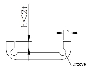
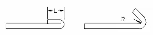
The height of the straight edge on a bent part should not be excessively small, with a minimum height of h > 2t.
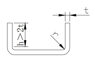
Regarding the minimum value of the straight edge height of a bending part:
If the design calls for a straight edge height of h ≤ 2t, the bending height should first be increased, and then cut down to the required size after bending.
Alternatively, a shallow groove can be processed in the bending deformation area, followed by a secondary bend (as shown in the accompanying figure).
In special cases, the straight edge height may require an oblique angle on the side of the bend.
When the side of a bending part has an oblique angle (as shown in the accompanying figure), the minimum height of the side should be h = (2-4)t > 3mm.
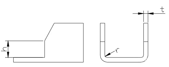
Height of straight edge with beveled edge
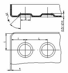
The hole edge distance on bent parts:
The hole should be punched first and then bent.
The hole’s position should be outside the bending deformation area to prevent deformation during bending.
The distance from the hole wall to the bending edge can be found in the accompanying table.
 |  | ||
| t(mm) | s(mm) | 1(Mm) | s(mm) |
| ≤2. | s≥t+r | ≤25 | s≥2t+r |
| >25~50 | s≥2.5t+r | ||
| >2 | s≥1.5t+r | >50 | s≥3t+r |
Height of straight edge with beveled edge
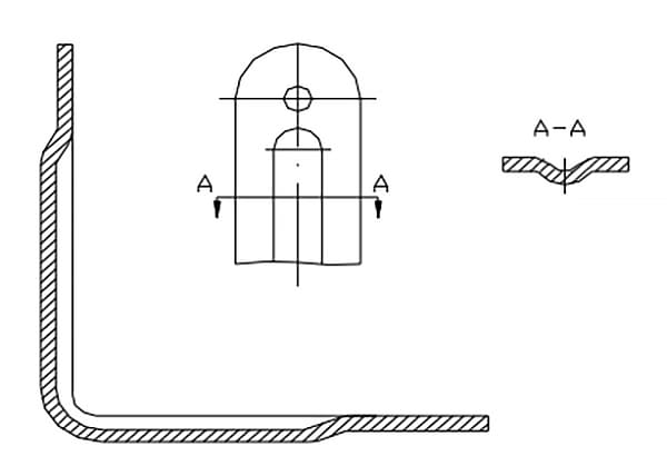
When a section of the edge is locally bent by a locally bent process notch, to prevent stress concentration from causing a bending crack at the sharp corner, the bend can be shifted a certain distance to eliminate the sudden change in size (as shown in Figure a), or a process groove (as shown in Figure b) or process hole (as shown in Figure c) can be punched.
Please note the dimensional requirements in the drawing: s ≥ R; groove width K ≥ t; groove depth L ≥ t + R + K/2.
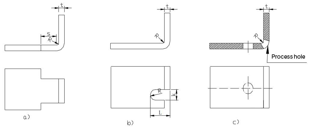
The design and processing method for local bending when a hole is in the bending deformation area uses the notch form as an example.
Example of notch form
The bending edge with a beveled edge should be positioned outside the deformation area.
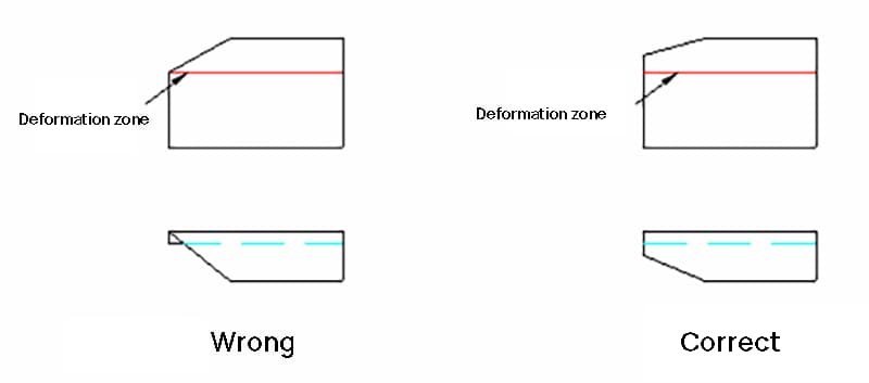
The bending edge with beveled edge shall avoid the deformation area.
The design of the dead edge must consider the dead edge length in relation to the material thickness.
As depicted in the accompanying figure, the minimum length (L) of the dead edge is typically ≥ 3.5t + R.
Here, t represents the wall thickness of the material, and R represents the minimum inner bending radius of the previous process (as shown in the right figure) before the dead edge is formed.
Minimum length of dead edge (L)
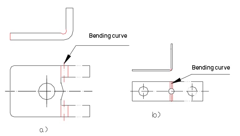
Process positioning holes are added in the design to ensure accurate positioning of the blank in the mold and avoid waste caused by deviation during bending.
As shown in the accompanying figure, process positioning holes should be included in the design in advance.
For parts formed through multiple bends, process holes must be used as a positioning reference to minimize accumulated error and guarantee product quality.
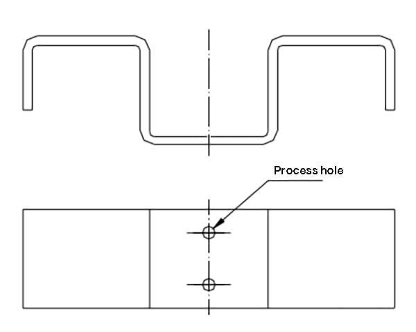
Process positioning holes added during multiple bending
When indicating the relevant dimensions of bent parts, the process must be taken into consideration.
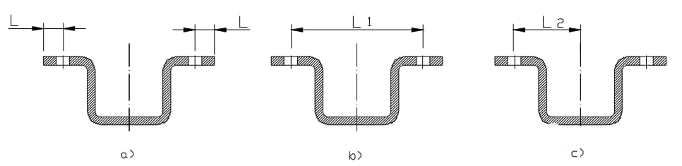
For example, as shown in the accompanying figure:
a) If the punching is performed before bending, the accuracy of the L-dimension is easily ensured and the processing is straightforward.
b) and c) If a high level of accuracy for the L-dimension is required, the holes must be machined before bending, which is more cumbersome.
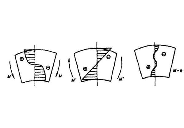
There are several factors that impact the springback of bending parts, including the material’s mechanical properties, wall thickness, bending radius, and positive pressure during bending.
The greater the ratio of the inner radius of the bent part to the plate thickness, the higher the springback.
An example of suppressing springback can be found in the design of the bending parts.
Currently, the manufacturer mainly uses design measures to prevent springback in the mold design.
Additionally, some structures are improved in the design to simplify the springback angle, such as adding a reinforcing rib in the bending area. This not only increases the rigidity of the workpiece but also helps to reduce springback.
Examples of methods for suppressing springback in design
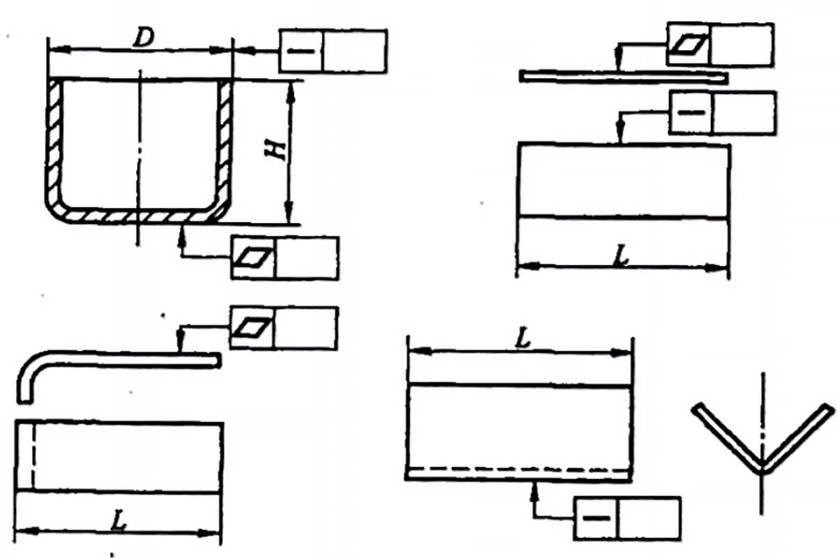
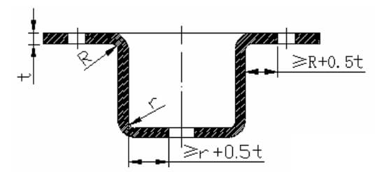
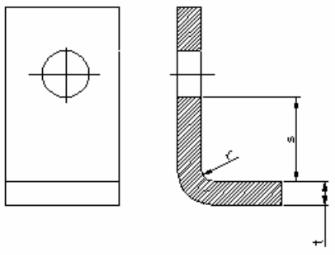
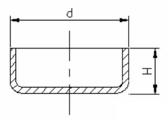
The fillet radius between the bottom of the stretched part and the straight wall should be as depicted in the accompanying figure.
The fillet radius between the bottom of the stretched part and the straight wall should be greater than the plate thickness, meaning r1 ≥ t.
For smoother stretching, r1 is typically set to (3 ~ 5)t, and the maximum fillet radius should be no more than 8 times the plate thickness, i.e. r1 ≤ 8t.
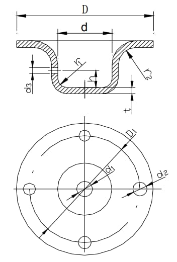
Example of bend dimension
The fillet radius between the flange and the wall of the stretched part should be greater than twice the plate thickness, meaning r2 ≥ 2t.
For smoother stretching, r2 is typically set to (5 ~ 10)t, and the maximum flange radius should not exceed 8 times the plate thickness, i.e. r2 ≤ 8t.
(refer to the above figure)
The diameter of the inner cavity of the circular stretched part should be at least d ≥ d + 10t to prevent wrinkling during stretching.
(refer to the above figure)
The fillet radius between adjacent walls of a rectangular stretched part should be r3 ≥ 3t.
To minimize the number of stretching times, r3 should be set to ≥ H / 5 as much as possible to allow for one-time stretching.
Fillet radius between two adjacent walls of rectangular stretching part
When forming a circular flangeless tensile part in one step, the height (h) to diameter (d) ratio should be less than or equal to 0.4, meaning H / d ≤ 0.4, as depicted in the below figure.
The dimensional relationship between the height and diameter of circular flangeless stretched parts during one-time forming.
Precautions for dimension marking on the design drawing of stretched parts:
Stretched parts are subjected to different levels of stress, which can lead to changes in material thickness after stretching. Typically, the center of the bottom maintains its original thickness, while the material at the bottom corner becomes thinner, the material near the flange at the top becomes thicker, and the material at the corner around the rectangular stretched part becomes thicker.
Reinforcing ribs on plate-shaped metal parts help to increase structural rigidity. The structure and size selection of reinforcing ribs is shown in the following figure.
| Name | Diagram | R | h | B or D | r | α ° |
| Stiffen | 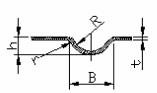 | (3~4)t | (3~2)t | (7-10)t | (1~2)t | – |
| Convex | 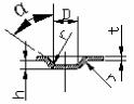 | – | (2~1.5)t | ≥3h | (0.5~1.5)t | 15~30 |
Structure and size selection of stiffeners
The limit dimensions for spacing and edge spacing of protuberances are indicated in the following table.
| Diagram | D | L | 1 |
 | 6.5 | 10 | 6 |
| 8.5 | 13 | 7.5 | |
| 10.5 | 15 | 9 | |
| 13 | 18 | 11 | |
| 15 | 22 | 13 | |
| 18 | 26 | 16 | |
| 24 | 34 | 20 | |
| 31 | 44 | 26 | |
| 36 | 51 | 30 | |
| 43 | 60 | 35 | |
| 48 | 68 | 40 | |
| 55 | 78 | 45 |
Structure of louvers
Size requirements of louvers: a ≥ 4t; b≥6t; h≤5t; L≥24t; r≥0.5t.
Louvers are commonly used on various covers or casings for ventilation and heat dissipation purposes. The forming method involves cutting the material with one edge of the punch and stretching and deforming the material at the same time with the rest of the punch to create an undulating shape with an opening on one side. The typical structure of louvers is depicted in the following figure.
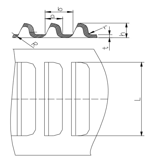
Structural louver size requirements: a ≥ 4t; b≥6t; h≤5t; L≥24t; r≥0.5t.
Internal hole flanging of machining thread
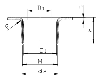
Schematic diagram of internal hole flanging structure with threaded hole
| screw thread | Material thickness (t) | Flanging inner hole D1 | Flanging outer hole d2 | Flange height (h) | Pre punching diameter D0 | Flange fillet radius R |
| M3 | 0.8 | 3.38 | 1.6 | 1.9 | 0.6 | |
| 3.25 | 1.6 | 2.2 | ||||
| 1 | 3.38 | 1.8 | 1.9 | 0.5 | ||
| 2.55 | 3.5 | 2 | 2 | |||
| 1.2 | 3.38 | 1.92 | 2 | 0.6 | ||
| 3.5 | 2.16 | 1.5 | ||||
| 1.5 | 3.5 | 2.4 | 1.7 | 0.75 | ||
| M4 | 1 | 4.46 | 2 | 2.3 | 0.5 | |
| 4.35 | 1.92 | 2.7 | ||||
| 1.2 | 4.5 | 2.16 | 2.3 | 0.6 | ||
| 3.35 | 4.65 | 2.4 | 1.5 | |||
| 1.5 | 4.46 | 2.4 | 2.5 | 0.75 | ||
| 4.65 | 2.7 | 1.8 | ||||
| 2 | 4.56 | 2.2 | 2.4 | 1 | ||
| 1.2 | 5.6 | 2.4 | 3 | 0.6 | ||
| M5 | 5.46 | 2.4 | 2.5 | |||
| 1.5 | 5.6 | 2.7 | 3 | 0.75 | ||
| 4.25 | 5.75 | 3 | 2.5 | |||
| 2 | 5.53 | 3.2 | 2.4 | |||
| 5.75 | 3.6 | 2.7 | 1 | |||
| 2.5 | 5.75 | 4 | 3.1 | 1.25 | ||
| 1.5 | 7 | 3 | 3.6 | 0.75 | ||
| 6.7 | 3.2 | 4.2 | ||||
| M6 | 2 | 7 | 3.6 | 3.6 | 1 | |
| 5.1 | 7.3 | 4 | 2.5 | |||
| 2.5 | 7 | 4 | 2.8 | |||
| 7.3 | 4.5 | 3 | 1.25 | |||
| 3 | 7 | 4.8 | 3.4 | 1.5 |
Internal hole flanging dimension parameters with threaded holes
Sheet metal processing is a method of cold working metal sheets to produce parts that meet specific requirements. Sheet metal parts offer several benefits, including strength, weight, cost-effectiveness, and improved performance compared to traditional components.
As a result, sheet metal parts have been increasingly utilized in high-tech industries such as electronics and communications in China.
However, demands for higher quality and functionality of sheet metal parts continue to rise. Thus, optimizing the original sheet metal processing technology has become a crucial focus for sheet metal processing professionals.
This paper believes that the optimization of processing technology should be approached systematically, starting with the application of the four fundamental cold processing links in sheet metal processing.
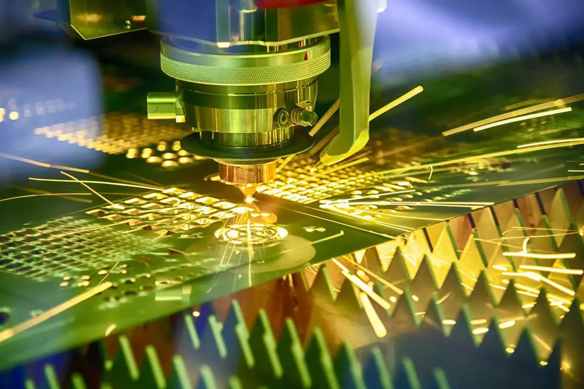
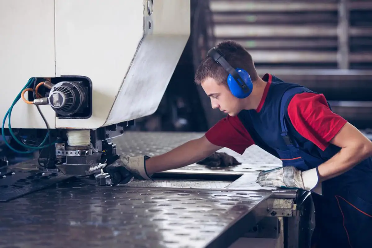
Blanking is the process of separating sheet metal materials from each other by punching with a die. This stage is typically used for processing parts with simple shapes, as it allows for a high degree of accuracy in the processing and minimizes material waste.
To optimize the blanking stage, the following factors should be considered:
The bending stage involves using bending equipment to apply pressure to sheet metal materials, causing them to undergo elastic deformation and then plastic deformation according to the desired design.
In this stage, different parts should be selected based on the design requirements, and the actual bending operation should be determined based on the thickness of the sheet metal.
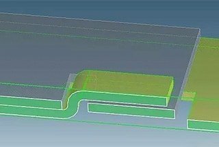
During the bending process, local abnormal deformation is often a common issue that can affect the appearance and functionality of the sheet metal parts. To optimize the bending process, the operator should make a cut in advance to prevent this type of deformation.
When multiple bends are needed, a comprehensive prediction should be made throughout all the bending stages to avoid any negative effects on subsequent bending processes and to achieve the desired design goal of the sheet metal parts.
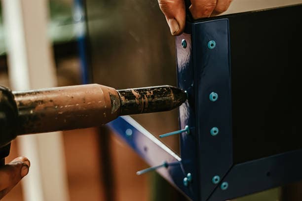
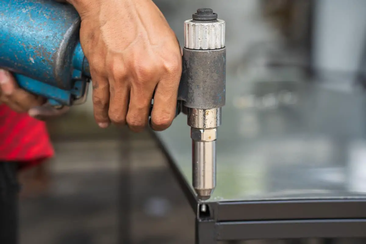
The press riveting process for sheet metal parts involves deforming the metal and coupling it together through pressure. This process is commonly used in screw press riveting and bolt press riveting.
For end press riveting operations, the nut typically has a circular shape with an embossed gear and wire slot section. This process not only optimizes the quality of the nut manufacturing process, but also eliminates the need for welding.
To achieve a better design outcome, the following steps should be taken:
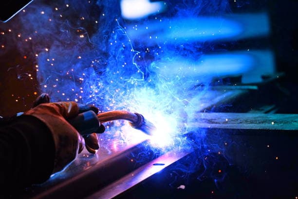
Welding is a crucial method for connecting the structures of parts in the cold working process of sheet metal processing. This process is typically performed under high temperature conditions.
The most commonly used welding methods are argon arc welding and contact spot welding.
In the welding process, different methods should be chosen based on the properties of the sheet metal parts to minimize welding deformation and improve efficiency.
To optimize the welding process, the following steps should be taken:

As the founder of MachineMFG, I have dedicated over a decade of my career to the metalworking industry. My extensive experience has allowed me to become an expert in the fields of sheet metal fabrication, machining, mechanical engineering, and machine tools for metals. I am constantly thinking, reading, and writing about these subjects, constantly striving to stay at the forefront of my field. Let my knowledge and expertise be an asset to your business.