Press Brake Hydraulic System Explained (diagram)
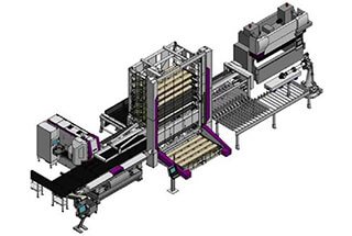
Have you ever wondered how a press brake's hydraulic system works? In this article, we'll dive deep into the intricacies of this essential component. Our expert mechanical engineer will guide…
Ever wondered how CNC press brakes achieve precise synchronization? This article delves into the electro-hydraulic system behind CNC press brakes, explaining how components like hydraulic cylinders and proportional valves work together to ensure high synchronization and accuracy. You’ll learn the principles, component roles, and operational phases, gaining insights into maintaining perfect alignment and performance in your press brake operations. Dive in to discover how these systems ensure precision in metal bending tasks.

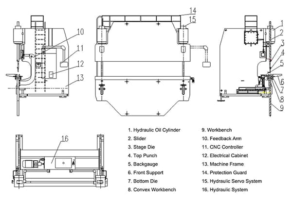
The electro-hydraulic synchronization system of the CNC press brake is comprised of the following eight components:
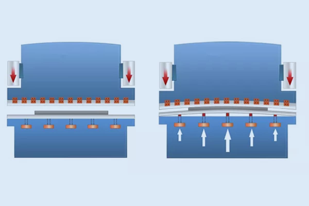
The position synchronization of the two piston cylinders during the stroke, and the positioning of the stroke endpoint, are achieved by the electro-hydraulic synchronous servo system, which has high synchronization and repeated positioning accuracy. Please refer to the figure below for the working principle of the press brake synchronization system.
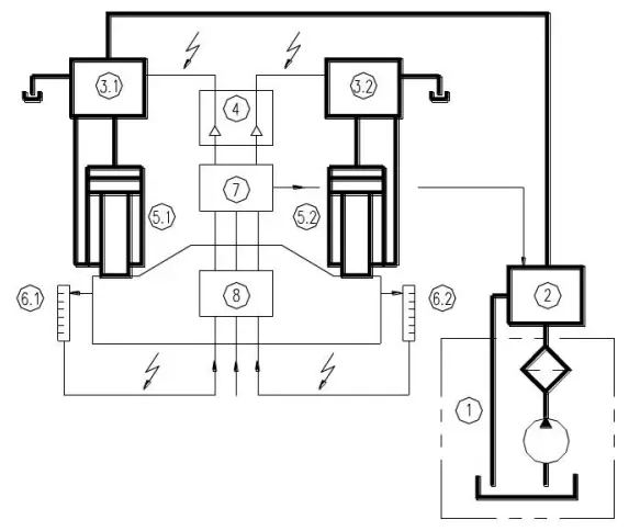
Fig. 2 Schematic diagram of synchronous control
The oil output from the drive assembly enters the hydraulic cylinders on both sides through the pressure control valve unit and the closed-loop control valve unit, drives the ram to move downward (or upward), and is detected and fed back to the CNC system and the electrical system through the position detection system at both ends of the ram. Then, the CNC system gives the processing signal to the closed-loop proportional valve amplifier, and the closed-loop control valve unit distributes the oil to the hydraulic cylinders at both ends to achieve synchronization at both ends of the ram. It has high synchronization and repeated positioning accuracy.
Please refer to the hydraulic schematic diagram of the CNC press brake (Fig. 3) and the action sequence table attached to the upper right corner for the hydraulic system principle and action sequence of hydraulic components of the CNC press brake machine.
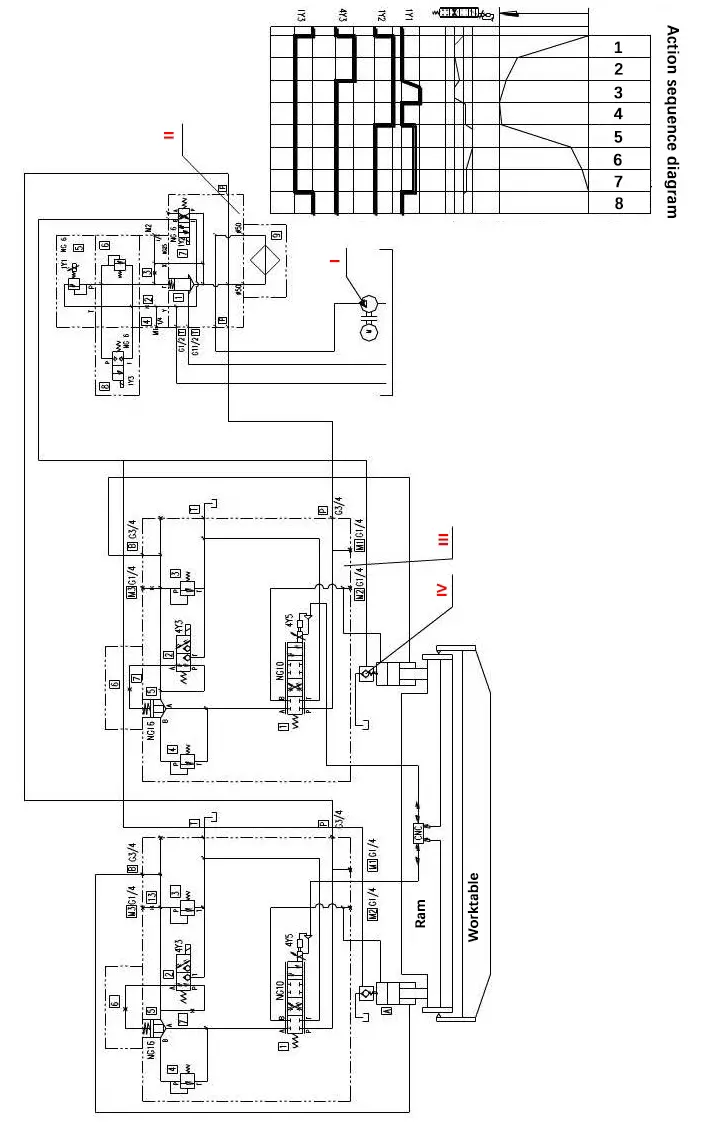
Fig.3 Hydraulic schematic diagram of the CNC press brake
Please refer to Figure 4 for the layout of the pressure control valve group of the hydraulic system and Figure 5 for the layout of the closed-loop control valve group. The component serial number and code in the figures are the same as those in Figure 3.
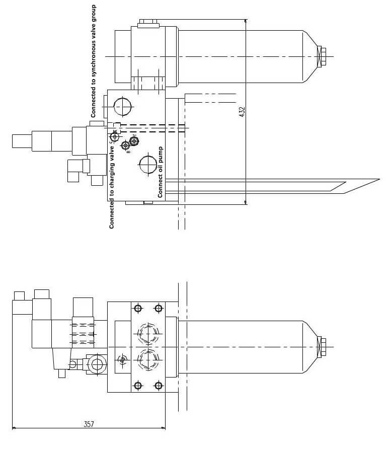
Fig4. Pressure control valve group of the hydraulic system

Fig.5 closed-loop control valve group
During machine operation, the ram needs to go through eight stages to complete one stroke:
Phase 1:
To power on 4Y3 and 4Y5, operate the down button.
When 4Y3 is powered on, port A and port T of lift valve (III-2) are connected, port P is closed, so the upper chamber of cartridge valve (III-5) is connected with the oil tank, and the cartridge valve (III-5) is open. When 4Y5 is powered on, ports P and B of proportional servo valve (III-1) are connected, ports A and T are connected, and the throttle port is set to the maximum.
Due to the opening of the (III-5) valve, the oil in the lower chamber of the two oil cylinders quickly returns to the oil tank through port A and T of the (III-5) valve and (III-1) valve, and the oil pressure required to support the ram is lost.
As a result of the self-weight of the ram, the piston drops rapidly, and the volume change rate of the upper chamber of the oil cylinder is greater than the flow of the oil pump, causing the upper chamber of the oil cylinder to generate negative pressure, and the oil in the oil tank is pressed into the upper chambers of the two oil cylinders through the filling valve (IV). The ram rapidly moves downward under no-load.
Phase 2:
When the ram quickly reaches the set value, provide 4Y5 with a new parameter value through the CNC system to reduce the throttle port of the proportional servo valve (III-1) and slow down the ram.
Phase 3:
Work advance boost:
4Y3 is powered off, 1Y2 is powered on, 4Y5 is powered on, and the proportional servo valve (III-1) is connected at ports P-B and A-T.
As 4Y3 loses power, the lifting valve (III-2) resets (port P-A is connected, and port T is closed), so the valve (III-5) is also closed, the oil circuit in the lower chamber of the oil cylinder is cut off, and the pressure required to support the ram is quickly generated, preventing the ram from falling freely.
1Y2 is powered on, connecting port P-A and port B-T of the reversing valve (II-7). Close the control port of the charging valve, close the charging valve, and cut off the passage between the upper chamber of the oil cylinder and the oil tank.
The oil output by the oil pump enters the upper chamber of the oil cylinder through the fine oil filter (II-9) and port P-B of the proportional servo valve (III-1). The proportional overflow valve (II-5) establishes pressure through the electromagnet 1Y1, forcing the ram to move downward against the supporting force and material pressing force of the lower chamber of the oil cylinder, while the oil in the lower chamber of the oil cylinder returns to the oil tank through port P-A of the overflow valve (II-5) and port A-T of the proportional servo valve (III-1).
This completes the pressing and boosting process.
Phase 4:
When the pressing is completed, 1Y2 remains powered on, 1Y1 loses power, and 4Y5 is powered on.
As 1Y1 is powered off, the system oil begins to relieve pressure while 4Y5 is powered on. The P, A, B, and T ports of the proportional servo valve (III-1) are closed to achieve force balance of the upper and lower cavities of the oil cylinder.
Phase 5:
After pressure relief, 1Y2 is powered off, and 1Y1 and 4Y5 are powered on.
As 1Y2 is de-energized, the directional valve (II-7) is reset, connecting port P-B and port A-T. Because port P-B is connected, the charging valve (IV) is opened to connect the oil return path between the upper chamber of the oil cylinder and the oil tank. 4Y5 is energized, and port P-A and port B-T of proportional servo valve (III-1) are connected.
At this time, the oil output by the oil pump flows into the lower chamber of the oil cylinder through the fine filter (II-9), port P-A of the proportional servo valve (III-1), the one-way valve (IV-11), and the valve (III-5), and the proportional overflow valve (II-5) establishes pressure through the electromagnet 1Y1, making the ram move upward rapidly. The hydraulic oil in the upper chamber of the oil cylinder returns to the oil tank through the charging valve (IV).
Phase 6 & 7:
As the ram rises to a certain position, 1Y1 continues to be powered on while changing the electrical signal of 4Y5 to adjust the opening of the proportional servo valve (III-1) and slowly close it to decelerate the rise and reach top dead center.
Phase 8:
When the ram reaches top dead center, 1Y1 loses power, and the ram stops running, completing a full stroke of the machine tool.
The synchronous servo system of a press brake machine controls the ram of the CNC press brake to always remain parallel to the workbench during rapid approach, working stroke, end point positioning, and return.
If the ram tilts due to various disturbances and eccentric loads, the position detection system at both ends of the ram detects and feeds back the deviation value to the computer, which adjusts the parameters such as the flow and pressure of the oil entering the oil cylinder through the proportional servo valve to keep the positions of the two pistons synchronized, ensuring that the ram remains parallel to the workbench.

As the founder of MachineMFG, I have dedicated over a decade of my career to the metalworking industry. My extensive experience has allowed me to become an expert in the fields of sheet metal fabrication, machining, mechanical engineering, and machine tools for metals. I am constantly thinking, reading, and writing about these subjects, constantly striving to stay at the forefront of my field. Let my knowledge and expertise be an asset to your business.