Press Brake Operation Manual (Training PDF)
Attention all mechanics and engineering enthusiasts! Have you ever wondered about the ins and outs of operating a press brake machine? In this blog post, we'll dive into the world…
1. Introduction At present, the global economy is in a slump and the manufacturing industry has been severely impacted. As a part of the manufacturing industry, the sheet metal industry is facing intense market competition in this economic climate. Quality is crucial for manufacturing enterprises to thrive in this intense competition. In many sheet metal […]
At present, the global economy is in a slump and the manufacturing industry has been severely impacted.
As a part of the manufacturing industry, the sheet metal industry is facing intense market competition in this economic climate.
Quality is crucial for manufacturing enterprises to thrive in this intense competition.
In many sheet metal manufacturing processes, bending is a crucial step that greatly impacts the quality of the final product.
Therefore, controlling the bending accuracy and stability is of great importance in improving the quality of sheet metal parts.
In the production process, the following issues may arise:
When a new die is used to bend sheet metal parts on the press brake, the parts initially meet the specifications outlined in the drawing.
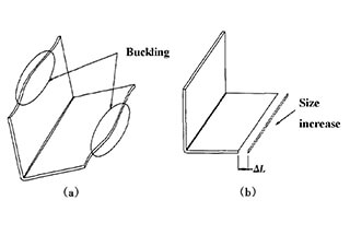
However, after a period of production, it is discovered that the parts bent using the same die no longer meet the specifications outlined in the drawing. This is primarily evidenced by two forms, shown in Figure 1a and Figure 1b.
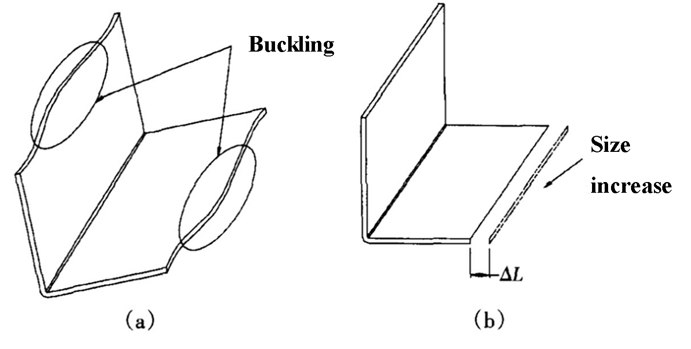
Fig. 1 Bending failure forms
a: Buckling deformation b: Size increase
Ultimately, the reason for the phenomenon shown in Figure 1 is due to the wear of the upper die of the press brake.
The upper die of a typical press brake is a general mold, and a set of general press brake upper dies can be used to bend a variety of sheet metal parts.
In other words, press brake upper dies are replaced less frequently, and the same group of bending upper dies is used for general bending. In some small factories, a single part may be used and the press brake die never changes.
Any tool or die will experience wear and tear over time, but the upper die of the press brake experiences a high frequency of use.
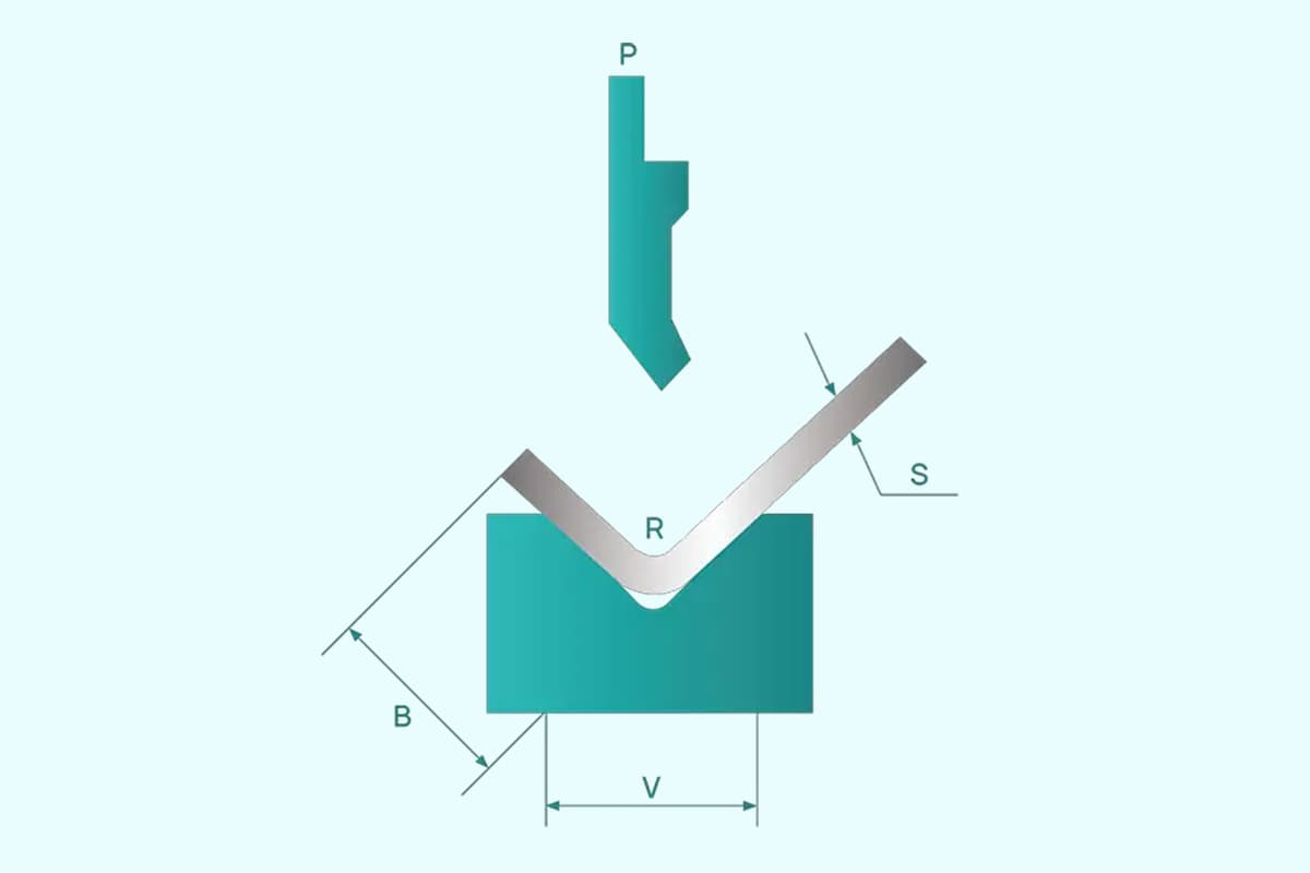
The R angle of a typical bending upper die is small, usually less than 0.5mm.
As a result, during bending, the pressure is concentrated entirely on the R angle of the upper die, causing a high level of stress at this point, making the upper die susceptible to wear.
As depicted in Fig. 2, the wear of the upper die results in an increase in the R angle.
In the calculation of parts unfolding, the R angle size in bending is one of the factors affecting the unfolding coefficient. Although the related information has been introduced, it has not been explained in detail in this context.
For the same part, the larger the R angle, the shorter the unfolding size will be.
Typically, there are two methods for selecting the bending expansion coefficient in factories:
The first method is more widely used, as it is fast and convenient for general parts bending.
The second method is usually used for parts with high bending accuracy and multiple bending angles, as the data obtained is more precise.
Regardless of the method used to obtain the expansion coefficient, it is usually solidified once determined.
For example, if the new upper die is used to bend SPCC with a material thickness of t = 1.0 mm, the expansion coefficient selected from the empirical table is 0.4. This expansion coefficient will remain at 0.4 for all materials with a thickness of t = 1.0mm that are bent using this upper die.
When the R angle wear of the upper die increases, the size of the part that was expanded using the expansion coefficient before the wear will inevitably become larger after bending, as shown in Fig. 1b.
This difference may not be noticeable for single angle bending, but if a part is bent multiple times in the same direction, the difference will accumulate. For example, if a part is bent six times in the same direction, the difference in unfolding will be 1.2mm, adding up to a 2mm dimension difference after bending.
To cut costs, many factories use medium carbon steel to manufacture bending upper dies, which have poor wear resistance. After using several dies, the R angle may increase from 0.5mm to almost 1mm.
The standard length of a single upper die for a press brake is 835mm, which is usually used in a group, depending on the type of press brake.
As illustrated in Fig. 3, a group of bending upper dies typically consists of three dies.
Many sheet metal processing factories produce miscellaneous parts of varying sizes, and the bending width can vary greatly.
Typically, sheet metal parts with a narrow bending width make up the majority. As a result, the middle section of the die is often used for bending, as shown in Fig. 3, leading to significant wear in the middle section.
When this group of dies is used to bend sheet metal parts with a large width, the pressure on both ends of the bending inner angle is greater than the pressure on the middle wear section, causing the inner angle R of the middle section to be greater than the angles at the two ends.
Increasing the pressure per unit area and reducing the bending angle R are effective ways to reduce springback.
However, the middle section has two factors that are favorable for springback. Since the springback in the middle section is greater than that at both ends, a “buckling” phenomenon, as shown in Fig. 1, may occur in the middle section.
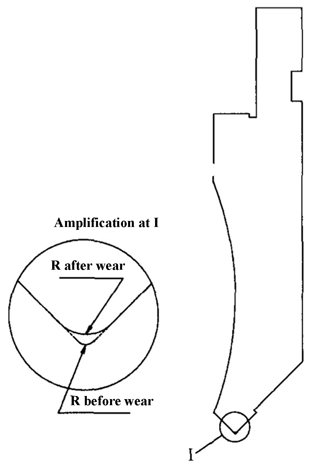
Fig. 2 Wear diagram of upper die
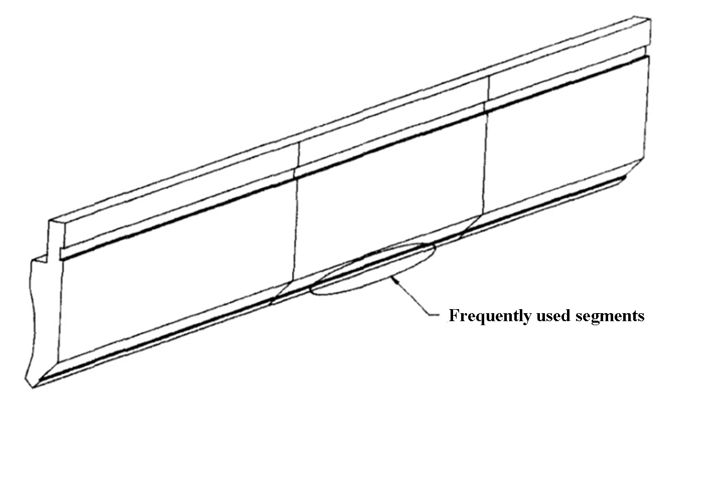
Fig. 3 Bending upper die
Die wear cannot be entirely eliminated, but by analyzing its causes and implementing appropriate measures, the two failure phenomena shown in Fig. 1a and Fig. 1b can be effectively controlled.
Based on production experience, the following five methods have been summarized:
These five methods can be selected based on the actual situation of the factory, and the effectiveness of each method may vary. The best method is the one that maximizes the benefits for the factory.
The sheet metal failure phenomenon discussed in this article is a common occurrence in the sheet metal manufacturing industry. It is hoped that through this article, more sheet metal manufacturing enterprises will take the necessary steps to prevent and avoid unnecessary losses.

As the founder of MachineMFG, I have dedicated over a decade of my career to the metalworking industry. My extensive experience has allowed me to become an expert in the fields of sheet metal fabrication, machining, mechanical engineering, and machine tools for metals. I am constantly thinking, reading, and writing about these subjects, constantly striving to stay at the forefront of my field. Let my knowledge and expertise be an asset to your business.