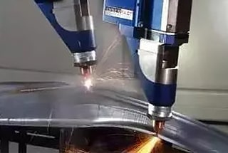
1. Projection welding principle
Projection welding is an efficient welding method that enables multi-point welding simultaneously. It can be used as an alternative to arc welding, brazing, and biting.
This method has the advantage of high processing speed with low consumption, only requiring power.
In comparison to spot welding, projection welding differs in that it involves pre-processing convex points on the plate or using profiles and chamfers that concentrate the current on the welding material as the contact points during welding.
During the welding process, the pressure and current density per unit area are increased through contact with the convex points, which helps to eliminate the oxide film on the plate surface, concentrate heat, reduce diversion, and decrease the center distance in spot welding. This allows for multi-point convex welding to be performed at once, improving productivity and reducing warpage deformation of the joint.
In automotive body manufacturing, projection welding nuts (nuts with bumps) are typically welded onto thin plates, allowing for easy assembly by only requiring bolt tightening, which improves assembly efficiency.
Projection welding is a resistance welding technique where one or more raised projections are pre-processed on the surface of one workpiece to make contact with the surface of another workpiece. An electric current is then applied, causing the projections to heat up and eventually collapse, forming a welded joint.
Projection welding is a variation of spot welding.
It is primarily used for welding low carbon steel and low alloy steel stamping parts. The ideal thickness range for projection welding of a plate is between 0.5 and 4mm, while spot welding is recommended for thicknesses less than 0.25mm.
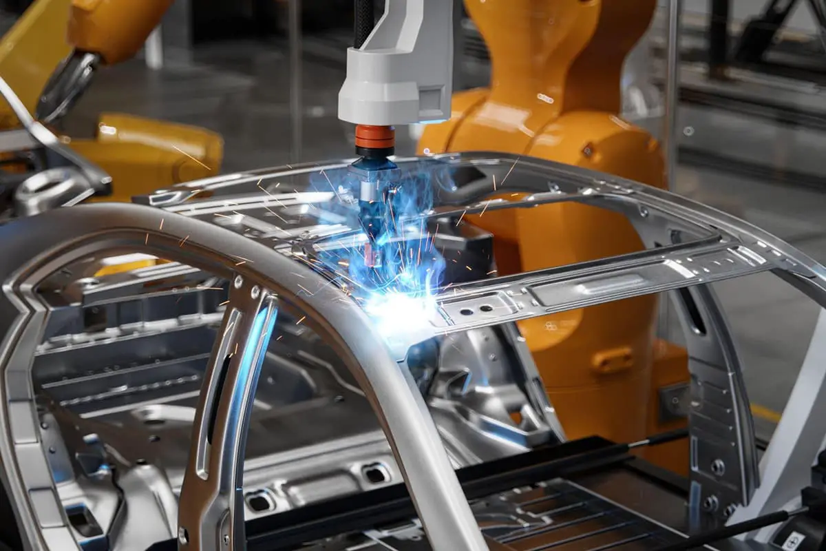
With the growth of the automotive industry, projection welding with its high productivity has become widely used in the production of automobile components.
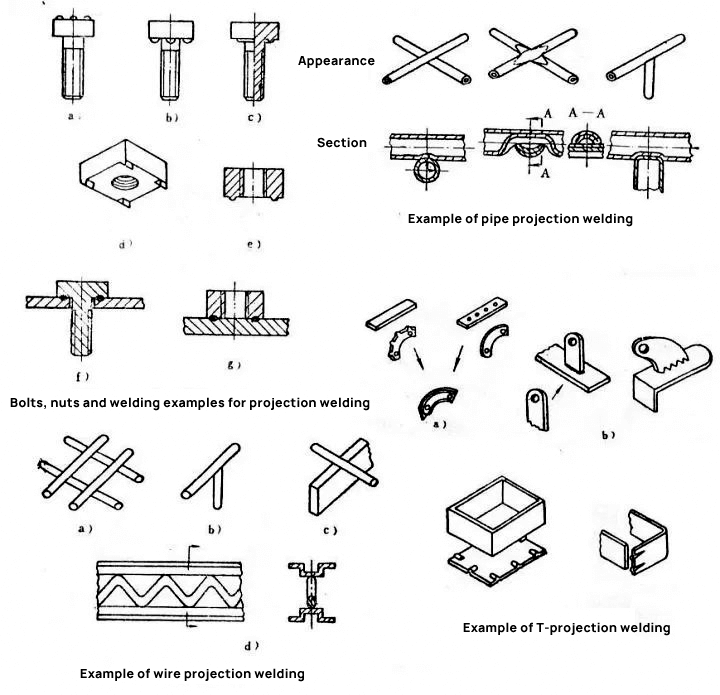
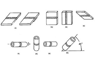
2. Classification of projection welding
Projection welding can be classified into several types including single point projection welding, multi-point projection welding, ring welding, T-shaped welding, roll projection welding, and wire cross welding.
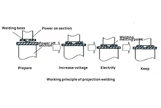
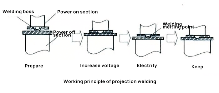
3. Three stages of bump formation
Projection welding is a resistance welding method that involves pre-processing one or more convex starting points on the surface of one workpiece to make contact with the surface of another workpiece. The workpieces are then pressurized and heated by electricity, causing the convex points to collapse and form a welded joint.
The formation of the bump joint is similar to spot welding and seam welding and can be divided into three stages: preloading, electrical heating, and cooling crystallization.
1. Preloading stage.
Under the influence of electrode pressure, the bonding surface between the projection and the bottom plate expands, stabilizing the conductive area of the welding zone and breaking down the oxide film on the bonding surface, resulting in a strong physical connection.
2. Power on heating stage.
The welding process consists of two stages: the crushing stage and the nucleation stage.
After the projection is crushed and the two plates are bonded, a large heating area is formed.
As the heating progresses, the melting of individual contact points expands, resulting in the formation of a melting core and plastic zone with sufficient size.
3. Cooling crystallization stage.
The nucleation process is similar to the nucleation welding process after the nucleation current is turned off.
4. Factors affecting projection welding quality
Welding Current: The amount of current required for each welding spot in projection welding is smaller than the amount required for spot welding the same spot. The maximum current is taken as the current that does not cause excessive metal extrusion under appropriate electrode pressure. The minimum current is the current that can melt the projection before it is fully crushed. The choice of welding current is mainly based on the material and thickness of the workpiece. In multi-point projection welding, the total welding current is the sum of the current required by each projection.
Electrode Pressure: The electrode pressure should cause the projections to collapse when they reach the welding temperature and ensure a close fit between the two workpieces. If the electrode pressure is too high, the projections will collapse prematurely, reducing the effectiveness of projection welding and weakening the joint strength due to decreased current density. On the other hand, too little pressure can result in excessive splashing. The size of electrode pressure affects both heat absorption and heat dissipation. The electrode pressure should be determined based on the material and thickness of the workpiece. It can typically be calculated as 1.5 times the sum of all points, provided that the projection reduction is no more than 10% when the power is turned off.
Electrode Pressure Fault Point: The electrode pressure fault point is between 500 to 800 N for a plate thickness of 1mm and between 5000 to 6000 N for a thickness of 5mm.
Welding Power On Time: This refers to the time that the welding power is applied to a spot. The welding power on time for projection welding is longer than that for spot welding. To shorten the welding power on time, the welding current should be increased, but excessive current can cause overheating and splashing. For a given material and thickness of the workpiece, the welding energization time should be determined based on the welding current and the stiffness of the projection. Typically, the power on time for single point welding is between 0.5 to 2.5 seconds. For workpieces thicker than 3mm, multiple power on times, such as 3 to 5 times, each with a duration of 0.04 to 0.8 seconds, with intermittent periods of 0.06 to 0.2 seconds, can be used to prevent overheating of individual points.
Welding Power: The electric power required for welding each spot varies based on the thickness of the workpiece. For a workpiece 1mm thick, the power required is between 40 to 50 KW, and for a 3mm thick workpiece, the power required is between 80 to 100 kW. When welding workpieces with the same metal, the projection should be punched on the thicker workpiece. When welding different metals, the projection should be punched on the workpiece with higher conductivity to achieve a heat balance between the two workpieces.
5. What are the advantages and disadvantages of projection welding
Advantages of Projection Welding:
- Multiple welding spots can be welded in one process, limited only by the control ability for adjusting current and force.
- Projection welding allows for welding of narrow flanges, as it has a large current concentration and limited opportunities for shunting at the welding spot, with a closer welding spot spacing compared to spot welding.
- The electrode contact surface in projection welding is larger than its projection and also larger than the electrode contact surface used in spot welding with the same nugget diameter, which results in lower electrode maintenance due to the reduced current density.
- Projection welding can be applied to metals that are too thick for resistance spot welding (RSW) connections.
- The size and position of the projection can be selected flexibly, allowing for a thickness ratio between the projection and the workpiece of 6 (or greater) to 1. This is sometimes difficult to achieve with spot welding for workpieces with a thickness ratio of about 3 to 1.
- The process can be used for leak-proof joints, such as in ring projection welding.
Disadvantages of Projection Welding:
- Additional processes will be necessary unless the part can be pressed into the required shape when forming one or more protrusions on a workpiece.
- The alignment of the workpiece and the control of the bulge size (especially its height) must be kept within strict tolerances to ensure uniform quality of the solder joint when using the same electrode to weld multiple solder joints at once.
- When performing projection welding of multiple solder joints simultaneously, the distribution of the projection is restricted by the current’s shunt path, which may not align with the desired position.