Sheet Metal Joining Process: The Ultimate Guide
Have you ever wondered how sheet metal parts are joined together to create complex structures? In this blog post, we'll explore the fascinating world of sheet metal joining techniques. As…
How can we ensure secure and durable connections in sheet metal fabrication? This article explores various joining and fastening techniques, including TOX riveting, welding, and nail riveting. You’ll discover the pros and cons of each method, practical applications, and how they contribute to the strength and integrity of metal structures. Dive in to understand which techniques best suit your specific fabrication needs.
There are various types of connections, which can be divided into two categories based on whether they are removable after connection: removable connections and non-removable connections.
This chapter mainly discusses non-removable connections, including TOX riveting, welding, punching and riveting, and nail riveting.
1. Definition:
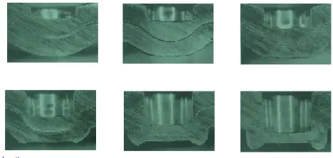
By using a simple convex mold, the connecting part is pressed into the concave mold. Under further pressure, the material inside the concave mold flows outward, resulting in a circular connection point that is smooth and without burrs.
This will not affect its corrosion resistance, even for plate materials with coatings or painted layers. This is because the coatings and paint layers also deform and flow along with the material.
The material is squeezed towards both sides and into the plate on the concave mold side, forming a TOX connection point, as shown in the diagram below:
2. Connection Method:
TOX riveting can be used to connect two or more layers of plates with the same or different materials and thicknesses.
Under the same conditions, the static connection strength of a TOX single point is 50%-70% of spot welding, and the strength of double points is the same as spot welding.
3. Connection Range of Different Rivet Points: (unit mm)
| Rivet diameter | 12 | 10 | 8 | 6 | 5 | 4 | 3 |
| Range of material thickness for connection | 4~11 | 1.75~7 | 1.6~6.0 | 1.0~3.0 | 0.9~2.5 | 0.6~2.0 | 0.5~1.5 |
| Minimum distance from the edge to the center of the TOX rivet | 10 | 8 | 7 | 6 | 6 | 5 | 4 |
Note: The TOX rivet diameter is closely related to the connection strength. The larger the diameter, the stronger the connection.
4. Defects of TOX Riveting:
(1) Relies on positioning fixtures or mold blocks for positioning.
(2) The minimum width of the connected material is affected by the diameter of the TOX mold.
5. Advantages of TOX Mold:
In addition to being used in specialized equipment, it is also suitable for ordinary punch presses, so its riveting range is much larger than what TOX requires.
For plate materials with coatings or painted layers, the protective layer at the connection point is not damaged, and the original anti-corrosion properties are retained.
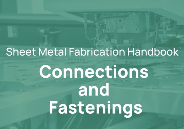
6. Schematic Diagram of TOX Rivet Forming:
The essence of the welding process is to use appropriate physical and chemical processes to bring the metal atoms of two separated surfaces close to the lattice distance (0.3-0.5nm), forming a metallic bond, so that the two metals are connected into one and achieve the purpose of welding.
In the manufacturing process, Tungsten Inert Gas Arc Welding (TIG), Metal Inert Gas Arc Welding (MIG), and spot welding are the most common welding methods. The following is a brief introduction of these three welding methods:
A. Tungsten Inert Gas Arc Welding
TIG welding is a welding process in which the electrode and arc zone, as well as the molten metal, are all protected by argon gas, isolating them from the air.
The electrode is made of tungsten or a tungsten alloy rod, and it does not melt during the arc burning process, resulting in a stable welding process.
When helium gas is used as the shielding gas, it is called helium arc welding.
TIG welding is widely used in industries such as aircraft manufacturing, atomic energy, chemical engineering, and textiles.
It is suitable for welding easily oxidized non-ferrous metals and their alloys, stainless steel, high-temperature alloys, titanium and titanium alloys, and hard-to-melt reactive metals such as molybdenum, niobium, and zirconium.
However, the current-carrying capacity of tungsten electrodes is limited, and the arc power is restricted, resulting in shallow welding depth, low welding speed, and only suitable for welding workpieces with a thickness of less than 6mm.
B. Metal Inert Gas Arc Welding
MIG welding, also known as Gas Metal Arc Welding (GMAW), uses a welding wire as the electrode, and the electrode and arc zone are protected by an inert gas such as argon.
If Ar-O2, Ar-CO2, or Ar-CO2-O2 is used as the shielding gas, it is called Metal Active Gas (MAG) welding.
MIG welding can weld almost all metals and is especially suitable for welding aluminum and its alloys, copper and its alloys, stainless steel, etc.
Since a welding wire is used as the electrode, a high-density current can be used, resulting in a large molten depth and fast filling speed.
It is suitable for welding thick aluminum and copper plates, and the welding deformation is smaller than TIG welding.
MIG welding can also use DC reverse connection and has good cathodic sputtering effect when welding aluminum and its alloys.
In addition, the inherent self-adjusting effect of the subsonic arc is more significant in MIG welding when welding aluminum and its alloys.
C. Spot Welding
Spot welding is a welding process in which the contact surface and its surrounding area of the joint are melted by the resistance heat generated by the contact between the electrodes and the workpiece, and then solidified to form a weld spot.
It can be used for mixed welding of aluminum and iron, aluminum and copper, stainless steel and cast iron, but it is more difficult to spot weld aluminum and aluminum.
D. Brazing
Brazing is a method of joining two or more pieces of metal by using a filler metal with a lower melting point than the base metal.
The filler metal melts and wets the base metal by capillary action, forming a strong joint upon solidification.
Brazing requires heating and protection to prevent the molten filler metal from coming into contact with the air.
There are several types of brazing methods according to different heat sources and protection conditions, such as flame brazing, induction brazing, resistance furnace brazing, salt bath brazing, etc.
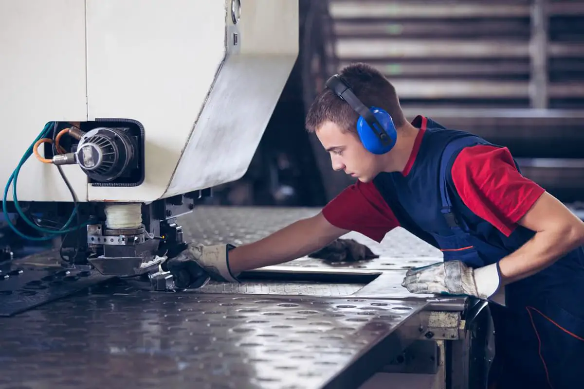
The existing welding equipment can be roughly divided into three types: spot welding machines, manual welding machines (MIG & TIG), and welding robots (MIG & TIG).
A. Spot Welding Machine:
Fixed C-type spot welding machine:
Qilong 100KVA AC IC synchronous control spot welding machine
Panasonic 100KVA AC microcomputer-controlled secondary current compensation spot welding machine (Japanese technology, produced by Panasonic Tangshan)
The above spot welding machines can weld galvanized steel plates, cold-rolled steel plates, stainless steel plates, horse-mouth iron, hot-rolled steel plates, with a thickness range of 0.3mm-6mm for lap joint of two plates.
Suspended spot welding machine:
Quanxing brand 48KVA suspended spot welding machine (produced in Taiwan), can weld plate thickness range of 0.2-3mm for lap joint of two plates.
Capacitor storage type spot welding machine:
Pengyuwei 4500J capacitor storage type spot welding machine, can weld aluminum and aluminum alloy plates with a thickness of 0.4mm-3.0mm.
B. MIG manual welding machine:
There are OTC 350P DC pulse MIG welding machine and American Flymat MIG350A welding machine, which can weld soft steel with a plate thickness of 0.8mm or above, and aluminum and aluminum alloys with a thickness of 2mm or above.
C. TIG manual welding machine:
Hitachi HITACHI AC/DC dual-use pulse TIG welding machine, which can weld soft steel with a plate thickness of 0.4mm or above, and aluminum and aluminum alloys with a thickness of 1.0mm or above.
D. MIG welding robot:
There are Swedish ABB MIG welding robots and Japanese YAKAWA company MOTOMAN WF200 MIG welding robots, which can weld galvanized steel plates, cold-rolled steel plates, stainless steel plates, horse-mouth iron, hot-rolled steel plates, with a thickness range of 0.8mm or above.
E. TIG welding robot:
There are Swedish ABB TIG non-filler welding robots, which can weld galvanized steel plates, cold-rolled steel plates, stainless steel plates, horse-mouth iron, hot-rolled steel plates with a thickness of 0.4mm or above.
Welding symbols and welding method codes are standardized symbols or codes used on welding structural drawings, and they constitute a kind of engineering language.
The welding symbols and welding method codes in China are defined in the national standards GB324-88 “Welding Symbol Representation Method” and GB5185-85 “Representation Codes of Welding and Allied Processes on Drawings.
These standards are basically consistent with the international standards ISO2553-84 “Welding Symbol Representation Method” and ISO4063-78 “Representation of Welding and Allied Processes on Diagrams”.
Therefore, they can be used interchangeably.
I. Welding Symbols
The GB324-88 “Welding Symbol Representation Method” standard specifies that welding symbols are applicable to both fusion welding and resistance welding.
The standard also specifies that to simplify the drawing, welding symbols should generally be used to represent welds on the drawing, but technical drawing methods can also be used.
The welding symbols specified by the national standard include basic symbols, supplementary symbols, and weld size symbols.
Welding symbols are generally composed of basic symbols and reference lines, and supplementary symbols, weld size symbols, and other symbols can be added as necessary.

Basic symbols represent the cross-sectional shape of the weld. The 13 basic symbols specified in the GB324-88 standard are shown in Table 1-3.
Welding supplementary symbols represent surface features of the weld. The three supplementary symbols specified in the GB324-88 standard are shown in Table 1-4.
Welding additional symbols are used to supplement certain features of the weld. The additional symbols specified in the GB324-88 standard are shown in Table 1-5.
Weld size symbols represent the characteristic dimensions of the groove and weld. The 16 size symbols specified in the GB324-88 standard are shown in Table 1-6.
Table 1-3: Basic Welding Symbols.
| Serial number | Name | Schematic diagram | Symbol |
| 1 | Edge weld (complete fusion of the edge) |  | |
| 2 | I-shaped weld | 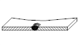 |  |
| 3 | V-shaped weld |  | |
| 4 | Single-sided V-shaped weld |  | |
| 5 | V-shaped weld with blunt edge |  | |
| 6 | Single-sided V-shaped weld with blunt edge |  |  |
| 7 | U-shaped weld with blunt edge |  | |
| 8 | J-shaped weld with blunt edge |  | |
| 9 | Seam weld |  | |
| 10 | Corner weld | 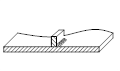 | |
| 11 | Plug weld or slot weld | 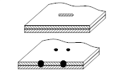 | |
| 12 | Spot weld |  | |
| 13 | Butt weld |  | |
Table 1-4: Welding Auxiliary Symbols
| serial number | name | schematic diagram | symbol | instruction |
| 1 | Flat symbol |  | Flush weld surface(generally achieved through machining) | |
| 2 | Concave symbol |  | Concave weld surface | |
| 3 | Convex symbol | 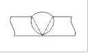 | Convex weld surface |
Table 1-5: Supplementary Welding Symbols
| serial number | name | schematic diagram | symbol | instruction |
| 1 | Backing bar symbol |  |  | To indicate a weld with a backing bar at the root |
| 2 | Stitch weld symbol |  |  | To indicate a weld on three sides |
| 3 | Circumferential weld symbol |  | To indicate a weld around the circumference of a workpiece | |
| 4 | On-site symbol |  | To indicate welding performed on site or in the field | |
| 5 | Tail symbol” is the translation for | 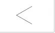 | You can refer to the content of GB5185 for marking welding process methods, etc. |
Table 1-6: Welding Dimension Symbols
| serial number | name | schematic diagram | serial number | name | schematic diagram |
| d | Workpiece thickness | 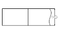 | aa | Bevel angle |  |
| b | Root gap | 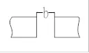 | l | Weld length” is the translation for |  |
| p | Blunt edge | 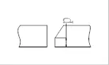 | n | Weld segment number |  |
| c | Weld width |  | e | Weld spacing | 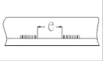 |
| d | Fusion diameter |  | K | Weld leg size | 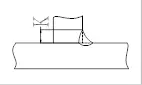 |
| S | Effective throat thickness |  | H | Depth of the groove |  |
| N | Quantity symbol for identical welds |  | h | Reinforcement height |  |
| R | Root radius |  | b | Bevel angle of the groove face | 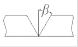 |
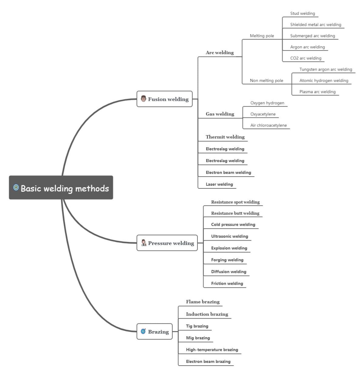
2. Welding Method Codes
In order to simplify the marking and description of welding methods, various welding methods such as metal welding and _ welding can be represented by Arabic numerals specified in the national standard GB5185-85.
Table 1-7 shows the codes of commonly used welding methods specified in the national standard GB5185-85.
Table 1-7: Codes for commonly used major welding methods.
| Welding Method Names | Welding Method Codes | Welding Method Names | Welding Method Codes |
| Arc welding | 1 | Pressure welding | 4 |
| Shielded metal arc welding (SMAW) | 111 | Friction welding | 42 |
| Submerged arc welding (SAW) | 12 | Diffusion welding | 45 |
| Gas tungsten arc welding (GTAW) with inert gas shielding, also known as Tungsten Inert Gas (TIG) welding | 131 | Other welding methods | 7 |
| Gas metal arc welding (GMAW) with inert gas shielding, also known as Metal Inert Gas (MIG) welding | 135 | Electroslag welding (ESW) | 72 |
| Gas metal arc welding (GMAW) with non-inert gas shielding, also known as Metal Active Gas (MAG) welding | 141 | Electrogas welding (EGW) | 73 |
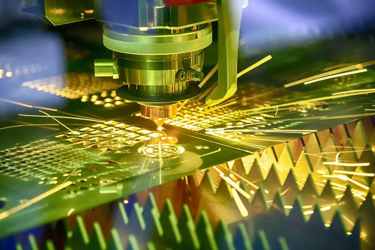
| Plasma arc welding (PAW) | 15 | Laser welding | 751 |
| Resistance welding | 2 | Electron beam welding | 76 |
| Spot welding | 21 | Stud welding | 78 |
| Seam welding | 22 | Hard soldering | |
| Flash welding | 24 | Hard brazing | 9 |
| Resistance butt welding | 25 | Soft soldering | 91 |
| Gas welding | 3 | Brazing. | 94 |
| Oxy-fuel welding. | 311 | – | – |
3. Welding Symbol Placement on Drawings
3.1 Basic Requirements:
The complete method of representing welds on drawings includes not only the basic symbols, auxiliary symbols, supplementary symbols, but also reference lines, some dimension symbols and data.
Weld symbols and welding method codes must be accurately represented through reference lines and relevant specifications.
Reference lines generally consist of two parts: an arrow line with an arrowhead and two baseline parts (one solid line and the other dashed line).
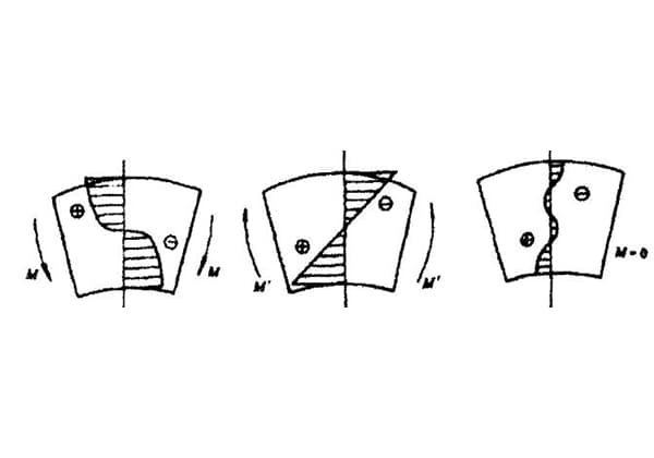
3.2 Relationship between Arrow and Joint:
The following figure provides an example of the meaning of the arrow side and non-arrow side of a joint:

The Position of Arrow Lines:
There is usually no special requirement for the position of arrow lines relative to welds, but when indicating V, single V, and J-shaped welds, the arrow line should point to the side of the workpiece with the groove. If necessary, the arrow line may bend once.
3.4 Position of Baseline:
The dashed line of the baseline can be drawn on the upper or lower side of the solid line of the baseline. The baseline should generally be parallel to the bottom edge of the drawing, but it can also be perpendicular to the bottom edge under special conditions.
3.5 Position of Basic Symbols relative to Baseline:
If the weld and arrow line are on the same side of the joint, the basic symbol of the weld should be marked on the solid line side.
For example, as shown in the following figure:
If the weld is on the non-arrow side of the joint, then the basic symbol of the weld should be marked on the dashed line side of the baseline.
When marking symmetrical welds and double-sided welds, it is not necessary to add dashed lines.
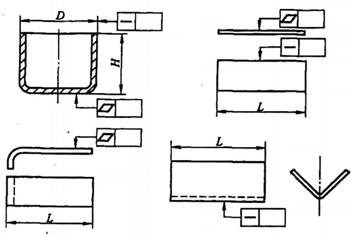
4. Weld Size Symbols and Their Annotation Positions:
4.1 The principles for marking weld size symbols and data are shown in the following figure:
The size on the cross-section of the weld is marked on the left side of the basic symbol.
The size in the length direction of the weld is marked on the right side of the basic symbol.
Sizes such as groove angle, groove face angle, and root gap are marked on the upper or lower side of the basic symbol.
The symbol for the number of identical welds is marked at the tail.
When there are many size data that are difficult to distinguish, the corresponding size symbol can be added in front of the data.
The above principles remain unchanged when the arrow direction changes.

4.2 Explanation of Dimension Symbols:
The dimensions that determine the location of the weld are not given in the weld symbol, but are marked on the pattern.
When there is no annotation or explanation on the right side of the basic symbol, it means that the weld is continuous along the entire length of the workpiece.
When there is no annotation or explanation on the left side of the basic symbol, it means that the butt weld must be fully penetrated.
For plug welds and slot welds with beveled edges, the dimension of the bottom of the hole should be indicated.
1. Understanding the Drawing:
In the manufacturing process, when the process design personnel receive the drawing, the first step is to understand the structure of the workpiece.
Based on this, understand the welding content required by the customer, including the welding location, welding method to be used, whether polishing is required, and other special requirements.
It is very important to understand the customer’s intention, which determines the process flow we will adopt later on.
2. Determining the Welding Method:
In general, the customer’s drawing has already clearly marked the welding method and requirements: whether to use soldering or spot welding, how long the weld seam should be, the cross-sectional size, etc.
However, in some cases, such as when we think that changing from soldering to spot welding would be better, we can confirm the change in welding method with the customer.
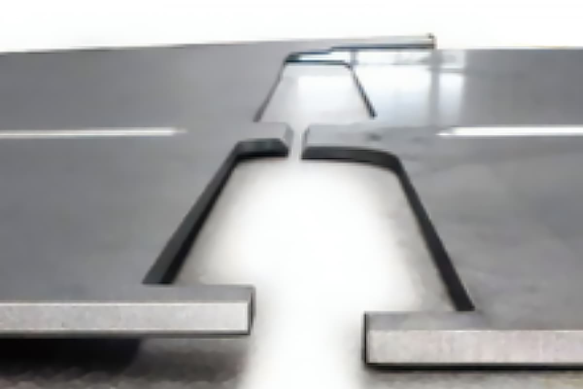
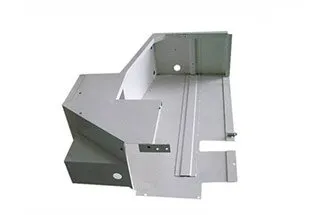
3. Determining the Welding Joint:
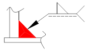
The most common welding joint is when the two sides of the workpiece intersect vertically when self-welding. As shown in Figure 1 below:

Note that in most cases, customers may not have considered weldability, and the joint may not necessarily meet the actual welding requirements.
Therefore, adjustments are generally required when welding in cases such as 90-degree perpendicular joints.
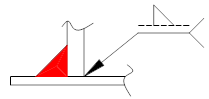
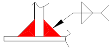
As shown in Figures 2 and 3, Figure 2 is most suitable for TIG welding with thin materials (less than 2.0), while Figure 3 is suitable for MIG welding with thick materials.
As for the edge wrapping form, it can be determined based on the actual situation, generally considering the bending angle, and it is best to use the long side to wrap the short side.
4. Welding Positioning:
When welding two or more workpieces, a relationship that can determine the position of each other is required, which is the positioning problem.
According to whether the workpiece itself has a positioning structure, it can be divided into self-positioning and fixture positioning.
The following describes these two types of positioning separately:
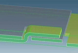
(1) Self-positioning:
A certain protrusion or reserved step is made on one workpiece, and the corresponding recess or hole is made on the other workpiece to realize the positioning between the workpieces.
Currently, there are two most commonly used types: half-shear – concave pit positioning and tenon – square groove positioning.
The typical structure of the half-shear – concave pit positioning is shown in the figure below.
In cases where the requirements are not high (such as when the welded surface of the workpiece is not visible), the concave pit can be processed into a through-hole, but it is strictly forbidden to make a through-hole if the workpiece is exposed to the outside.
Another alternative structure of this method is to make the circular half-shear and concave pit into a rectangle, but this is not recommended.

The processing of half-shear and concave pit is generally carried out in NCT. Both specifications of half-shear, whether upward or downward, have tooling.
There is no dedicated tooling for front concave pits, but they can be processed through the use of combination tools.
There is a dedicated tooling for reverse concave pits with a diameter of 3.1, but there is currently no tooling for reverse concave pits with a diameter of 2.4, and they cannot be processed.
The method of using half-shear – concave pit positioning has certain limitations: due to the adoption of the half-shear structure, the half-shear effect is not ideal for thick plates (above T2.0), and the protruding part of the half-shear is arc-shaped and cannot serve as a limiting function.
And because the concave pit is formed by forcibly squeezing the material, it can only be applied to relatively soft materials (such as AL, CRS, GI, etc.), and it is impossible to achieve this for harder materials (such as SPHC, SUS, etc.).
In summary, this method is suitable for materials with a range of 2.0mm or less of GI, CRS, and AL sheet metal.
Tenon – square groove positioning is shown in the figure below:

When using this type of positioning method, the first step is to determine the specifications of the positioning groove.
If NCT cutting is used, it is best to consider that the square hole can be machined in one pass with NCT tooling.
If laser cutting is used, the size can be determined based on the actual situation. Generally, the slot hole can be 0.1mm larger than the tenon, and the protruding part of the tenon must not exceed the thickness of the plate at the positioning groove.
The slot does not necessarily have to be a rectangular hole (closed type) and can be made as an open type depending on the specific situation.
(2) Application range of two self-positioning methods:
Comparing the above two positioning methods, it can be seen that when the welding surfaces of two workpieces are parallel to each other, the half-shear and concave pit positioning method is better.
When the welding surfaces of two workpieces are perpendicular to each other, the tenon – square groove positioning method is more suitable.
(3) Fixture positioning:
If self-positioning cannot meet the requirements of the drawing or high positioning requirements are needed, a special clamping fixture needs to be made, and cooperation with relevant departments (such as automation research and development) is required.
5. Process requirements for spot welding:
(1) Total thickness of spot welding:
The total thickness of spot welding must not exceed 8mm, and the size of the welding spot is generally 2T+3 (2T represents the thickness of the two welded parts).
Since the upper electrode is hollow and cooled by cooling water, the electrode cannot be reduced without limit, and the minimum diameter is generally 3-4mm.
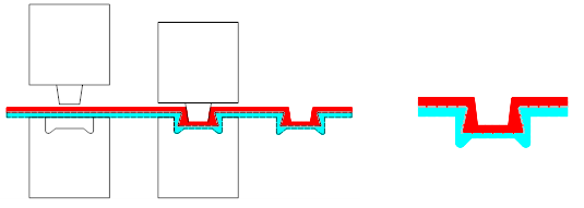
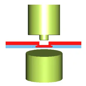
(2) Punching and burring of welding spots:
The workpiece of spot welding must punch and burr welding spots on one of the surfaces that are in contact with each other to increase welding strength.
Usually, the size of the burr is Φ1.5-2.5mm, and the height is about 0.3mm. Processing some small protrusions on one of the workpieces to be welded can improve the welding process.
As shown in the figure below, when the welding head presses on the protrusion during the welding process, and electricity is applied, the small protrusion is melted, making the connection tighter and more reliable.
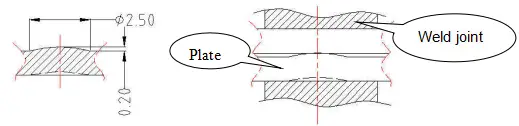
(3) Distance between two welds:
As the thickness of the welded workpiece increases, the distance between the two welds also increases.
If the distance is too small, the workpiece is prone to overheating and deformation, while if it is too large, the strength of the joint may be insufficient and cracks may appear between the two workpieces.
Generally, the distance between two welds should not exceed 35mm (for materials below 2mm).
(4) Gap between welded workpieces:
Before spot welding, the gap between the two workpieces should generally not exceed 0.8mm.
When the workpiece is bent and then spot welded, the position and height of the welds are very important.
If they are not properly placed, the spot welding may be misaligned or deformed, resulting in larger errors.
(5) Surface damage caused by spot welding:
Burrs are easily formed at the spot welding point, which need to be polished and rustproofed.
When necessary, the spot welding area can be coated with silver paint. If the spot welding area needs to be painted, it must be polished before painting.
(6) Spot welding of galvanized steel plates:
Galvanized steel plates mainly include galvanized plates, lead-coated plates, aluminum-coated plates, and tin-coated plates, etc.
In production, spot welding of galvanized steel plates and galvanized parts is commonly encountered.
The thickness of the zinc layer is generally below 20um.
Compared with spot welding of ordinary steel plates, the presence of the zinc coating not only reduces the current density in the welding area but also makes the distribution of the current field unstable.
Increasing the current also further promotes the formation of Cu-Zn alloy on the working end face of the electrode, accelerating the electrode wear and coating damage.
At the same time, the low-melting-point zinc coating causes cracks and pores to occur during the crystallization process of the fusion zone.
Therefore, the suitable spot welding specification range for galvanized steel plates is narrow, and the joint strength fluctuates greatly, with poor weldability.
(7) Interference processing range of spot welding:
The following is a schematic diagram of spot welding by a welding machine, with the data indicating the processing range provided by the spot welding group on October 16, 2000.

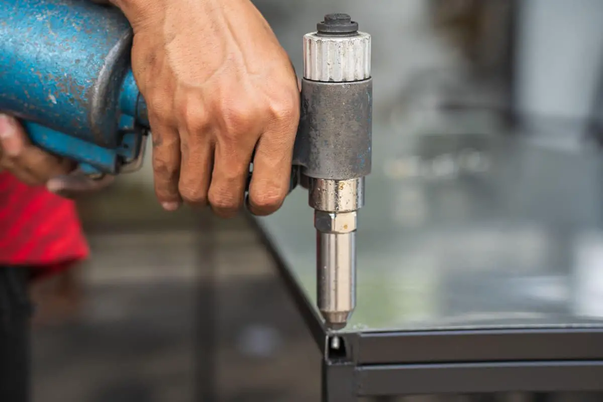
1. Definition
Hole extrusion riveting is a process that connects two parts, one with a punched hole and the other with a countersunk hole, using a riveting die to form an inseparable joint.
Advantages: Punching and countersinking provide inherent positioning for the two parts. Hole extrusion riveting results in a high joint strength and high efficiency through the use of specialized tooling.
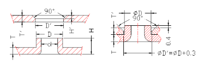
Countersunk Rivet Joint Data Sheet
| Item number Serial number | Material thicknessT(mm) | Countersink heightH(mm) | Countersink outer diameter D(mm) | |||||||||||
| 3.0 | 3.8 | 4.0 | 4.8 | 5.0 | 6.0 | |||||||||
| Corresponding to the countersink inner diameter d and pre-punched hole d0 | ||||||||||||||
| d | d0 | d | d0 | d | d0 | d | d0 | d | d0 | d | d0 | |||
| 1 | 0.5 | 1.2 | 2.4 | 1.5 | 3.2 | 2.4 | 3.4 | 2.6 | 4.2 | 3.4 | / | / | / | / |
| 2 | 0.8 | 2.0 | 2.3 | 0.7 | 3.1 | 1.8 | 3.3 | 2.1 | 4.1 | 2.9 | 4.3 | 3.2 | / | / |
| 3 | 1.0 | 2.4 | / | / | / | / | 3.2 | 1.8 | 4.0 | 2.7 | 4.2 | 2.9 | 5.2 | 4.0 |
| 4 | 1.2 | 2.7 | / | / | / | / | 3.0 | 1.2 | 3.8 | 2.3 | 4.0 | 2.5 | 5.0 | 3.6 |
| 5 | 1.5 | 3.2 | / | / | / | / | 2.8 | 1.0 | 3.6 | 1.7 | 3.8 | 2.0 | 4.8 | 3.2 |
Note: The general principle of countersunk riveting is H=T+T’+(0.3~0.4), D=D’-0.3, and D-d=0.8T. When T≧0.8mm, the thickness of countersink wall is 0.4T. When T<0.8mm, the thickness of countersink wall is usually 0.3mm. H’ is usually taken as 0.46±0.12.
1. Classification:
Pull rivets are divided into two types: flat head and round head (also known as umbrella head).
For flat head pull rivets, the side in contact with the rivet head must have a countersunk hole. For round head pull rivets, the contact surface is flat.
2. Definition:
Pulling the mandrel of the rivet through the two parts with through-holes using a rivet gun until it breaks, causing the outer sleeve of the rivet to expand and become a non-removable connection.
3. Parameters of pull rivet joint:
| Category of rivets. | The nominal diameter of the rivet D | The diameter of the hole for riveting steel plates D1 | LengthL | M | Head diameter H | Head height P | Thickness of the steel plate for riveting | Ultimate strength.(N) | |||
| Umbrella-shaped | Flat head | countersunk | flat head with shear resistance | Shear resistance | tensile strength resistance | ||||||
| Aluminum blind rivet | 2.4 | 2.5 | 5.7 7.3 8.9 | 1.42 | 4.8 | 0.7 | 0.8 | 1.0~3.2 3.2~4.8 4.8~6.4 | 1.6~3.2 3.2~4.8 4.8~6.4 | 490 | 735 |
| 3.0 | 3.1 | 6.3 8.0 9.8 | 1.83 | 6.0 | 0.9 | 1.0 | 1.0~3.2 3.2~4.8 4.8~6.4 | 1.6~3.2 3.2~4.8 4.8~6.4 | 735 | 1180 | |
| 3.2 | 3.3 | 6.3 8.0 9.8 | 1.83 | 6.4 | 0.9 | 1.1 | 1.6~3.2 3.2~4.8 4.8~6.4 | 1.6~3.2 3.2~4.8 4.8~6.4 | 930 | 1420 | |
| 4.0 | 4.1 | 6.9 8.6 10.4 | 2.28 | 8.0 | 1.2 | 1.4 | 1.2~3.2 3.2~4.8 4.8~6.4 | 1.6~3.2 3.2~4.8 4.8~6.4 | 1470 | 2210 | |
| aluminum pull rivet | 4.8 | 4.9 | 7.5 9.3 11.1 | 2.64 | 9.6 | 1.4 | 1.6 | 1.6~3.2 3.2~4.8 4.8~6.4 | 2.3~3.2 3.2~4.8 4.8~6.4 | 2260 | 3240 |
| steel pull rivet | 3.2 | 3.3 | 6.4 9.5 | 1.93 | 9.5 | 1.0 | 1.0~3.2 3.2~6.4 | 1270 | 1770 | ||
| 4.0 | 4.1 | 10.2 | 2.41 | 11.9 | 1.25 | 3.2~6.4 | 2060 | 2940 | |||
| 4.8 | 4.9 | 10.8 | 2.90 | 15.9 | 1.9 | 3.2~6.4 | 2750 | 3920 | |||
Note: The diameter of the through-hole for the rivet in the part is usually 0.2~0.3mm larger than the nominal diameter D of the rivet. The distance from the center of the rivet hole to the edge should be greater than 2 times the size of the rivet hole for the best riveting strength. If the distance is too small, the strength will be greatly reduced.
4. Diagram of rivet shapes:
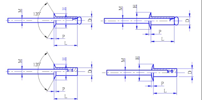
Note:
(1) Flat head pull rivets are mainly used for surfaces with strict requirements where no protruding fasteners are allowed to be connected. The flat head of the pull rivet is embedded in a countersunk hole on the fastener so that the head does not protrude from the surface.
(2) The color of the pull rivet can be matched with the assembly workpiece by blackening or other treatments to meet customer requirements. For example, the head of the pull rivet can be painted to allow for riveting on painted workpieces.
5. For the most commonly used pull rivet, 3B010-01
It is the open-end flat head pull rivet mentioned above. The outer diameter D of the rivet is 0.125 inches, which is 3.175mm. The corresponding countersunk hole is Φ6.5XΦ3.5X120°, and the through-hole matched with it is Φ3.4.

As the founder of MachineMFG, I have dedicated over a decade of my career to the metalworking industry. My extensive experience has allowed me to become an expert in the fields of sheet metal fabrication, machining, mechanical engineering, and machine tools for metals. I am constantly thinking, reading, and writing about these subjects, constantly striving to stay at the forefront of my field. Let my knowledge and expertise be an asset to your business.