Manual loading and unloading tasks are labor-intensive, pose risks for workplace injuries, and offer lower efficiency.
Moreover, they do not guarantee consistent product quality, failing to meet the high-volume, high-quality production demands of businesses.
Our company has implemented an automated production line for the sheet metal forming of door frames, integrating multiple machines operated by industrial robots. By pairing these robots with sheet metal equipment, we can automate processes such as material feeding, positioning, coordination with the sheet metal machines, handling, and finished product unloading.
This greatly reduces labor and material costs and enhances production efficiency.
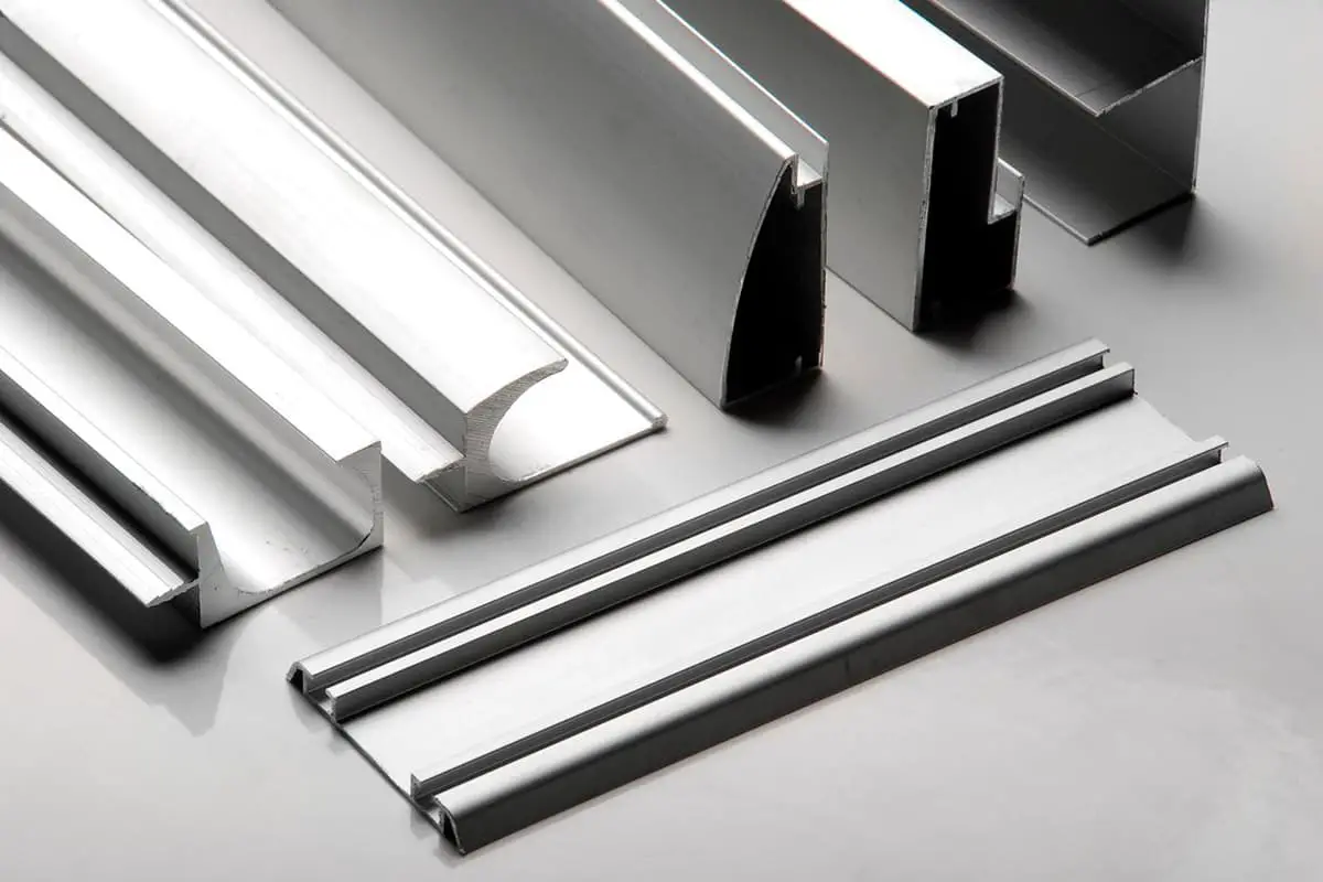
The door frame is an essential component of anti-theft security doors. The precision in forming the door frame directly impacts the security level and performance specifications of the door.
According to the national standard GB17565-2022 “Technical Conditions for Anti-Theft Security Doors”, door frames must adhere to the following specifications:
1. Based on the security grades of B, C, and D, the steel plate thickness for door frames should be 2.00mm, 1.80mm, and 1.50mm, respectively. The steel used must meet the tolerances specified in Table 1.
2. The diagonal dimensions of both the door frame and door leaf, as well as the tolerances for the frame’s groove and the door leaf’s exterior dimensions, should comply with the requirements in Table 2.
Size/mm
<1000
1000~2000
2000~3500
>3500
Tolerance range/mm
≤2.0
≤3.0
4≤
≤5.0
3. The overlap width between the door leaf and frame must be no less than 8mm. The door frame and door leaf, or other parts, may have an anti-intrusion device installed. The device and its connecting strength should withstand a 30kg sandbag impact test three times. Post-testing, no breakage or detachment should occur.
The national standard GB17565-2022 has set higher requirements for the material and precision of door frames. Traditional rolling processes do not meet these precision demands.
To address this, our company has developed a fully automated production line using a die pressing process for metal forming. This not only meets national standards but also increases product yield, boosts production efficiency, and reduces both labor and material costs.
Automation Production Line Overview
Equipment Introduction
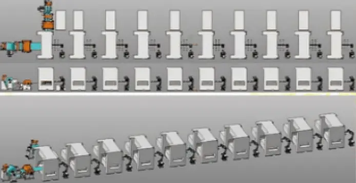
1. The sheet metal forming automated production line for door frames consists of ten six-axis robots, seven press brakes, two punching and trimming machines, two three-in-one feeders, one conveyor, one shearing machine, and one safety enclosure, spanning a total length of 65 meters. (Refer to Figure 1)
Figure 1: Automated Production Line for Sheet Metal Door Frame Formation
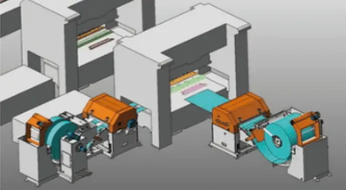
2. Material feeding is done using roll feeding. Two products on one side share a feeder, while a product on the opposite side uses a separate feeder. (Refer to Figure 2)
Figure 2: Method of Loading Coil Material
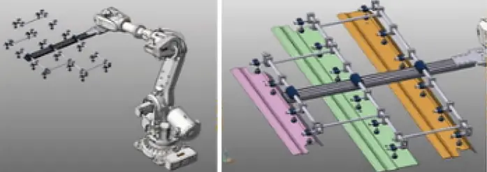
3. The pick-up method employs a modular suction cup end effector, versatile enough to handle a variety of products and easily adjustable. (Refer to Figure 3)
Figure 3: Combination Suction Cup End Picker Grabbing
4. Basic features of the robot units include:
A Chinese information interface, suitable for robot trajectory debugging and PLC program debugging.
Display of fault information, operational data, and production details for each unit.
Operational guidance and self-diagnosis information for each unit.
Each robot unit and press machine interlock during operations. PLC synchronization programs and sheet metal equipment slide position detection ensure the robots load and unload smoothly without interfering with the sheet metal machines.
Production Process
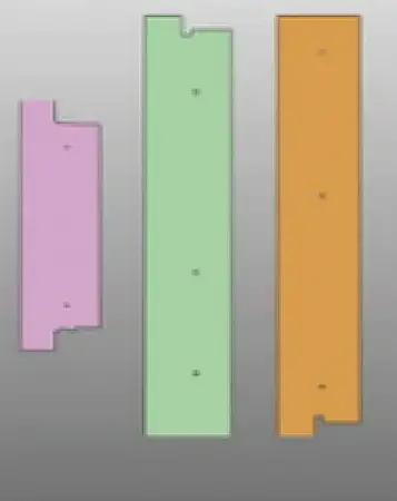
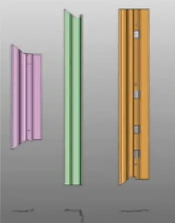
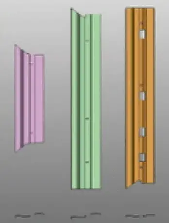
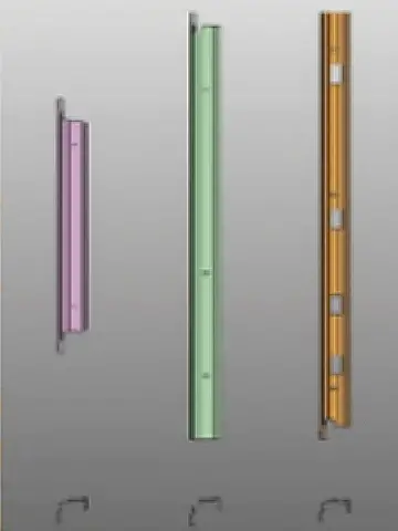
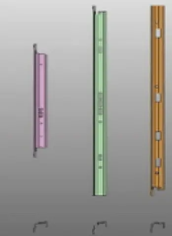
Based on the door frame product structure, our company analyzed the fabrication processes of its three components, comprising ten operations in total.
Step 1: A three-in-one feeder sends the metal sheet into the shearing machine. Once it reaches the set length, a signal is sent, and the shearer cuts the metal sheet. The machine then waits for the robot to retrieve the cut material, as shown in Figure 4.
Figure 4: Operation One: Unloading
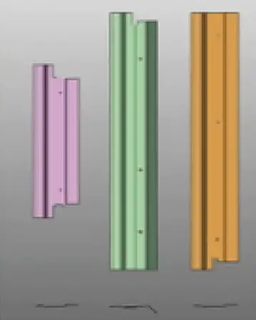
Step 2: Six-axis robot 1 transports the cut sheet to the mold of Press Brake A to start bending. Meanwhile, the robot returns to fetch another sheet, as illustrated in Figure 5.
Figure 5: Operation Two: Bending 1
Step 3: Six-axis robot 2 transfers the component from Press Brake A to Press Brake B. Upon receiving the signal, the machine begins the bending process. The robot then retrieves another piece, detailed in Figure 6.
Figure 6: Operation Three: Bending 2
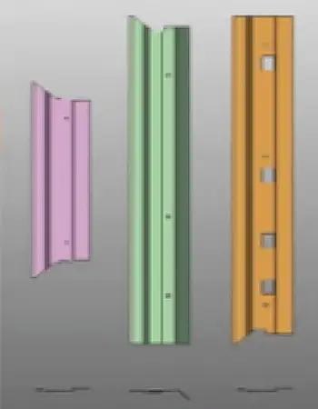
Step 4: After Press Brake B completes the bending, six-axis robot 3 places the part inside Punching and Edging Machine C to begin the punching and edging process. The robot subsequently fetches another part, as depicted in Figure 7.
Figure 7: Operation Four: Edge Cutting 1
Step 5: Once the punching and edging are completed, six-axis robot 4 moves the part from Machine C to Press Brake D. The bending process commences upon signal, with the robot returning for another part. See Figure 8 for reference.
Figure 8: Operation Five: Bending 3
Step 6: After bending in Press Brake D, six-axis robot 5 transfers the component to Press Brake E. The bending resumes after a signal prompt. Concurrently, the robot retrieves another piece, as highlighted in Figure 9.
Figure 9: Operation Six: Bending 4
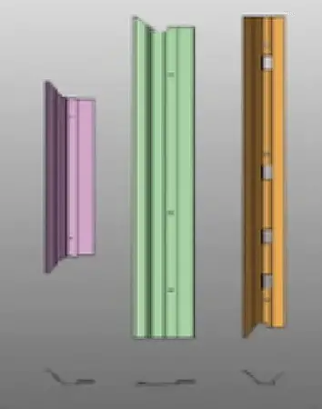
Step 7: Following the bending process in Press Brake E, six-axis robot 6 moves the component to Press Brake F, where bending ensues after signaling. The robot then fetches the next piece, shown in Figure 10.
Figure 10: Operation Seven: Bending 5
Step 8: Post bending in Press Brake F, six-axis robot 7 places the component back in Press Brake C for further bending. The robot then collects another piece, illustrated in Figure 11.
Figure 11: Operation Eight: Bending 6
Step 9: After Press Brake G’s bending operation, six-axis robot 8 shifts the component from Press Brake C to Press Brake H. Bending continues after a signal, with the robot fetching the subsequent part, detailed in Figure 12.
Figure 12: Operation Nine: Bending 7
Step 10: Once Press Brake H completes bending, six-axis robot 9 moves the component from the sheet metal bender to Punching and Edging Machine I to initiate punching, as seen in Figure 13. After punching, six-axis robot 10 transports the component to the assembly line, marking the completion of a production cycle.
Figure 13: Operation Ten: Punching 1
Central Control System
This automated line utilizes a centralized CPU control structure. The entire control system employs a strict hierarchical control. Without permission from the main operating station, equipment cannot operate independently.
Various intelligent sensors and readers communicate through buses with corresponding PLCs or remote I/O units. This includes onsite operation stations, field equipment detection units (proximity switches, photoelectric switches, etc.), other field input devices, and field actuators (like inverters, electromagnetic gaps, etc.).
Interlocking signals between the automation line PLC and the press machine PLC connect through buses or I/Os, while the line PLC exchanges data with the robot control system via a bus.
Operating Modes of the Entire Line
This automated production line operates in two modes: “Manual” and “Automatic.” Each operating station features an “Automatic/Manual” mode switch.
1. Automatic Mode:
A standard production mode with continuous sequential operations. In this mode, the sheet metal forming equipment operates in a single stroke manner, halting at the slider’s top dead center awaiting commands.
During the sheet metal equipment’s operational cycle, robots collect slider position data and complete the loading and unloading actions.
2. Manual Mode:
A maintenance and debugging mode that carries out all equipment actions following predetermined production trajectories.
Conclusion
Our company’s developed door frame sheet metal forming automated production line produces 7-8 pieces per minute, achieving component precision standards.
Compared to traditional production methods, efficiency increases by 30%, workpiece qualification rates rise by 25%, labor costs drop by 90%, and material costs reduce by 15%.
As the founder of MachineMFG, I have dedicated over a decade of my career to the metalworking industry. My extensive experience has allowed me to become an expert in the fields of sheet metal fabrication, machining, mechanical engineering, and machine tools for metals. I am constantly thinking, reading, and writing about these subjects, constantly striving to stay at the forefront of my field. Let my knowledge and expertise be an asset to your business.
Basic Concepts of Computer-Aided Design and Computer-Aided Manufacturing Computer-aided design and computer-aided manufacturing (CAD/CAM) is a comprehensive and technically complex system engineering discipline that incorporates diverse fields such as computer [...]
Concept of Virtual Manufacturing Virtual Manufacturing (VM) is the fundamental realization of the actual manufacturing process on a computer. It utilizes computer simulation and virtual reality technologies, supported by high-performance [...]
A Flexible Manufacturing System (FMS) typically employs principles of systems engineering and group technology. It connects Computer Numerical Control (CNC) machine tools (processing centers), coordinate measuring machines, material transport systems, [...]
Just as manufacturing technology plays a crucial role in various fields today, nanofabrication technology holds a key position in the realms of nanotechnology. Nanofabrication technology encompasses numerous methods including mechanical [...]
Ultra-precision machining refers to precision manufacturing processes that achieve extremely high levels of accuracy and surface quality. Its definition is relative, changing with technological advancements. Currently, this technique can achieve [...]
Currently, machining can be categorized into two groups based on production batch: Among these two categories, the first one accounts for about 70-80% of the total output value of machining [...]
This article mainly introduces several mature special processing methods. I. Electrical Discharge Machining (EDM) EDM is a method of machining conductive materials by utilizing the phenomenon of electrical corrosion during [...]
What is CNC machining? Numerical Control (NC) refers to the method of controlling the movement and processing operations of machine tools using digitized information. Numerical Control Machine Tools, often abbreviated [...]
Cutting machining remains the most prominent method of mechanical processing, holding a significant role in mechanical manufacturing. With the advancement of manufacturing technology, cutting machining technology underwent substantial progress towards [...]
1. What is welding stress Welding stress refers to the stress generated during the welding process in welded components. This stress is caused by the thermal process of welding and [...]
Advanced materials refer to those recently researched or under development that possess exceptional performance and special functionalities. These materials are of paramount significance to the advancement of science and technology, [...]
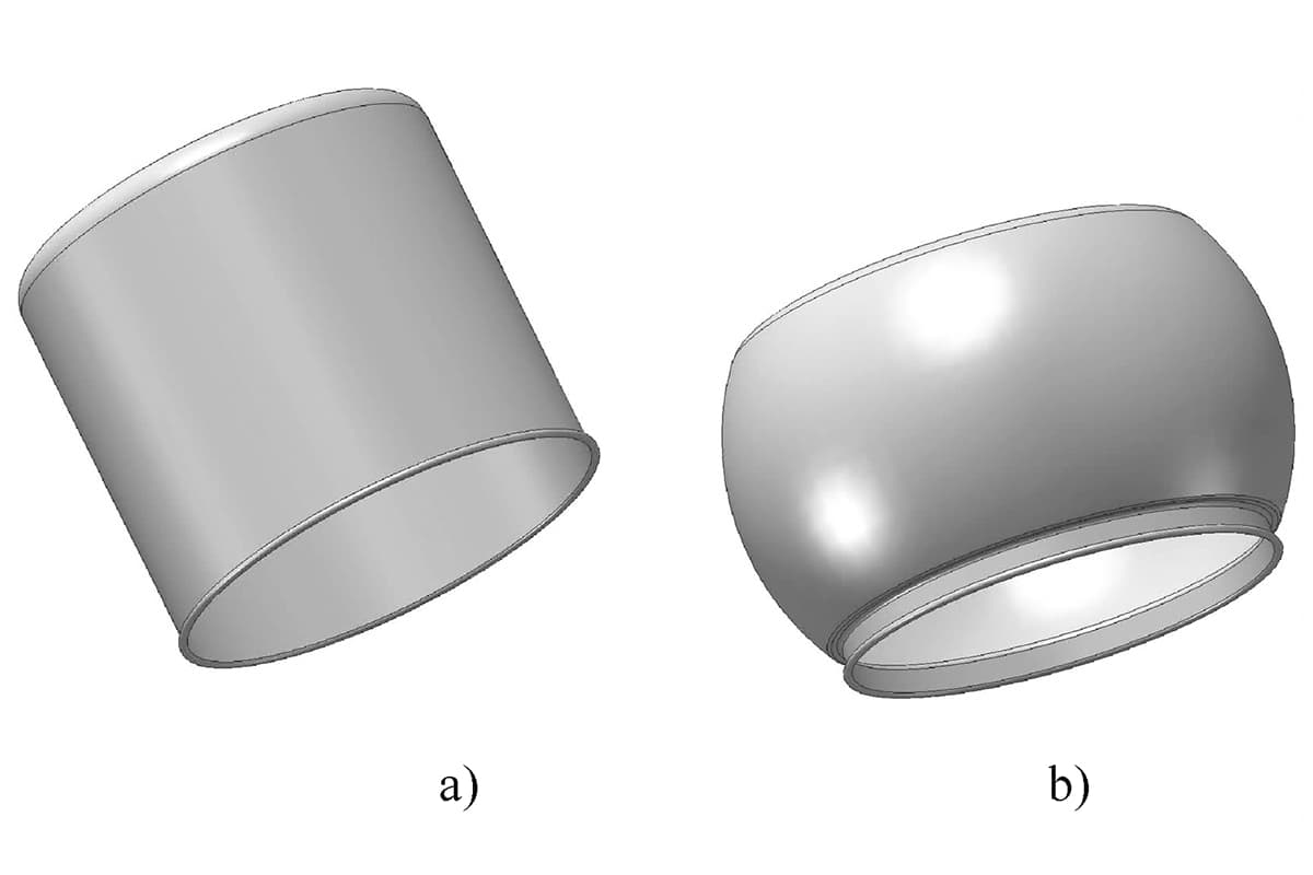
Bulge forming is suitable for various types of blanks, such as deep-drawn cups, cut tubes, and rolled conical weldments. Classification by bulge forming medium Bulge forming methods can be categorized [...]