Weld Seam Hardness Control: Tips and Best Practices
How can weld seam hardness impact the overall integrity of a structure? Ensuring the right hardness of weld seams is critical in welding, as it affects the toughness and durability of the joints. This article explores practical tips and best practices for controlling weld seam hardness, covering factors like interpass temperature, heat treatment, and welding processes. By following these guidelines, you’ll enhance weld quality and performance, avoiding common issues related to weld hardness. Dive in to learn how precise control can make all the difference in your welding projects.
The alloy content of SA335-P91 steel is wCr=9%, wMo=1%, wV=0.2%, wNb=0.08%, wN=0.05%.
It belongs to martensitic heat resistant steel, and its metallographic microstructure is low-carbon tempered martensite.
Due to the adoption of micro alloy control technology and other grain refining measures, it becomes a fine grain steel, which is not only conducive to improving the impact toughness of steel, but also extremely conducive to improving the high temperature creep strength of steel.
SA335-P91 is a martensitic fine grain steel, which makes the main problem of P91 steel welding different from other low alloy heat-resistant steels.
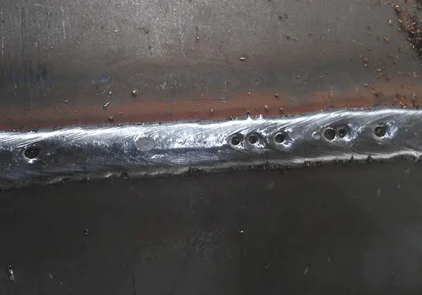
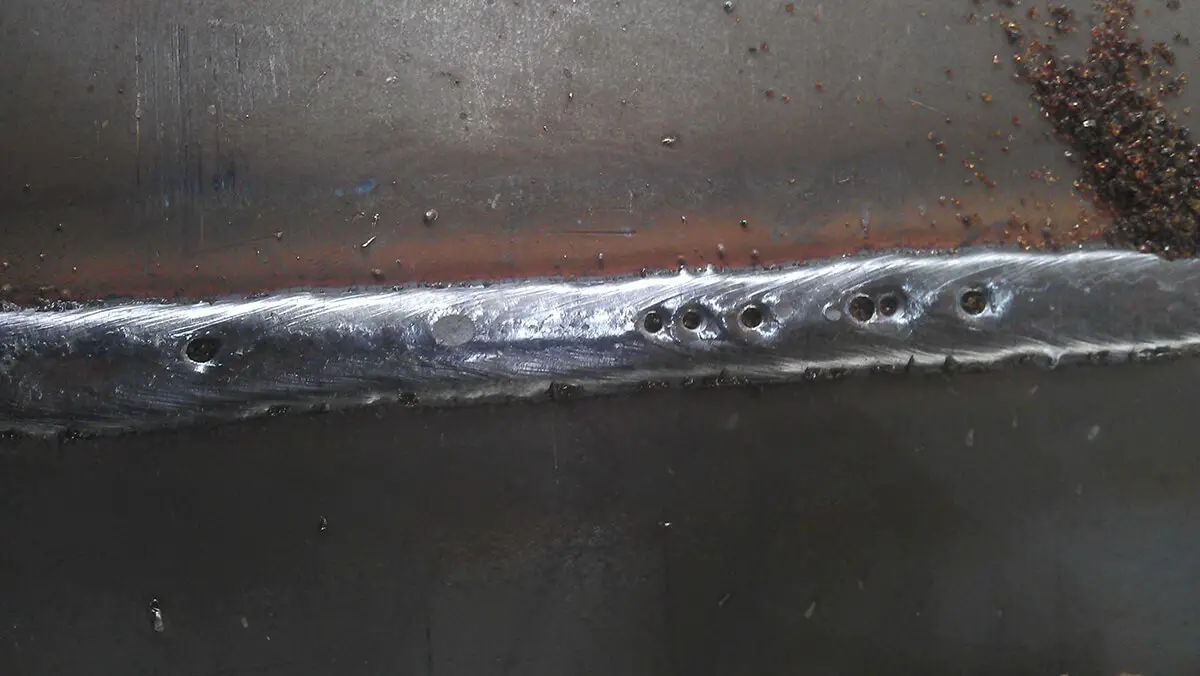
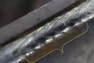
The weak link of welded joints is not in the fusion zone, but in the weld metal, it mainly shows that the toughness of the weld metal decreases and the weld hardness is high.
2. Process principle
(1) As SA335-P91 steel is fine-grain steel, if the interpass temperature is too high during welding, it will increase by 8/5, making its grains grow up and lose the original strength and toughness of the steel.
However, it is impossible to normalize it during on-site welding.
Therefore, the interpass temperature must be strictly controlled during welding to prevent grain growth.
(2) The heating width, constant temperature, constant temperature time, insulation width and the insulation thickness of heat treatment are the main factors affecting the weld toughness.
Properly increasing the heating width, insulation width, insulation thickness and constant temperature time will help to increase the tempering degree of the martensite structure and improve the weld toughness.
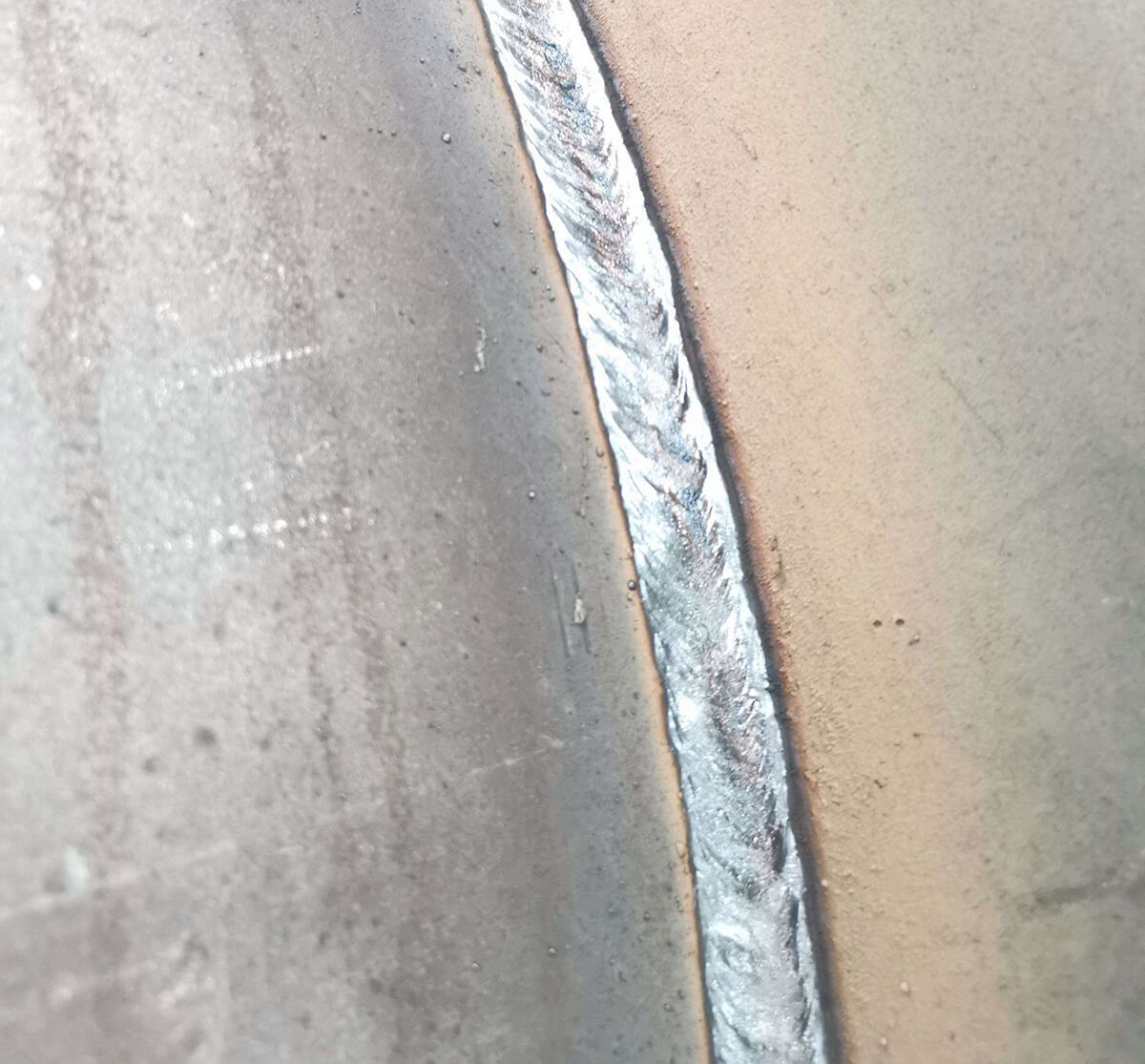
By increasing the welding speed, reducing the thickness of the weld bead, the wide swing fast thin layer welding method should be used.
(2) During welding, the technicians use a far-infrared temperature measuring gun to measure the interpass temperature of each layer of weld (the interpass temperature is the temperature 10~20mm in front of the molten pool, expressed by the highest value), and the interpass temperature is strictly controlled below 300 ℃.
When the far-infrared temperature measuring gun shows that the temperature exceeds 300 ℃, stop welding immediately, and continue welding when the temperature drops to 230 ℃.
After the welding of each layer is completed, the technician uses a vernier caliper to measure the weld bead thickening.
The maximum thickening is ≤ 3mm.
It is strictly prohibited to form a fillet weld between the groove and the weld bead.
4. Welding precautions
The welding current is selected according to the characteristics of the electrode.
For the electrode with coating transition, the electrode can be melted by using a smaller current, which can reduce the heat input.
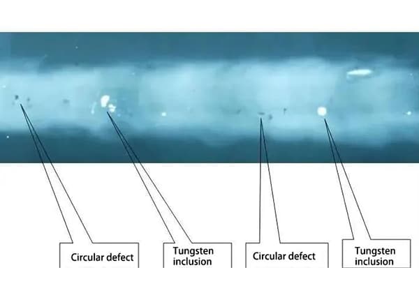
The disadvantage is that the tungsten melting point in the coating is high, which is easy to cause tungsten inclusion in the weld.
In a word, no matter which type of welding rod is used, it is necessary to ensure the fluidity of molten iron and the clear molten pool, especially the good fusion at the root of the groove.
On this basis, small specifications shall be used as far as possible.
5. Heat treatment process
The post welding heat treatment adopts the heat treatment machine DKPC-12360 - 12, which is heated by caterpillar ceramic resistor, and the thermocouple is bound and fixed.
K-type armored thermocouple, matched compensation wire and automatic temperature recorder are used, and aluminum silicate insulation cotton is used.
(1) Preheating before welding and interpass temperature control
Electric heating is adopted for preheating.
Four thermocouples are used to control the temperature.
The temperature control points are 3, 6, 9 and 12.
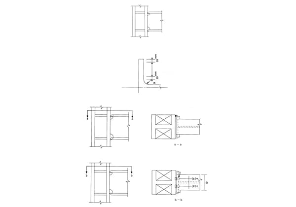
The thermocouple end is 20mm away from the weld groove edge (see Figure 1), and the preheating temperature is 150 ℃.
When the temperature reaches the constant temperature of 0.5h, the backing welding can be started to maintain the temperature balance and improve the weldability of the base metal.
During the shielded metal arc welding, the temperature rises to 230 ℃, the overtemperature alarm is set to 260 ℃, and the interpass temperature is required to be 200~300 ℃.
The heat treater monitors the temperature and immediately heats it if the temperature is too low.
If the temperature is too high, the welding shall be stopped immediately, and the welding shall be resumed when the temperature is restored to 230 ℃.
The interpass temperature shall be tracked and controlled by the heat treatment machine throughout the welding process.
Fig. 1 Thermocouple 20mm from groove edge during interlayer temperature control
(2) Post weld heat treatment
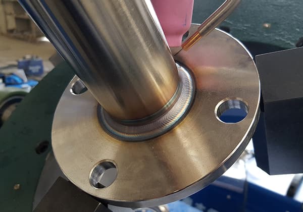
First, the thermocouple shall be in good contact with the weld during heat treatment.
The hot end of the thermocouple is generally placed on the first weld near the edge of the groove and must be firmly bound with 20 # iron wire to prevent the thermocouple from loosening due to thermal expansion at constant temperature, as shown in Fig. 2 and Fig. 3.
Fig. 2 Place the hot end of the thermocouple on the first weld to ensure good contact between the hot end and the weld
Fig. 3 Installation Diagram of Thermocouples for Temperature Control in Zone 4 and Zone 3 of PWHT
Second, during the installation of the heater, the weld beading, welding slag and spatter on the surface of the weldment shall be cleaned up to make the heater and the surface of the weldment close.
After the heater is installed, it shall be bound with 20 # iron wire to prevent the expansion of the heating strip at high temperature (see Fig. 4).
Fig. 4 The heater shall be bound with thick iron wire after installation
Third, increase the thickness and width of heat treatment insulation, and the insulation thickness is 100mm, as shown in Fig. 5.
Fig. 5 Thickness and Width of Heat Preservation by Increasing Heating Treatment
Fourth, for elbows, tees or welds close to valves and cylinder bodies, in addition to crawler heaters, rope heaters should also be used for auxiliary heating.
Wrap the rope heater at the position where the heater cannot contact the workpiece well, as shown in Fig. 6.
Fig. 6
Fifth, P91 pipe heat treatment parameters are shown in the attached table.
Reasonably increasing the constant temperature time, heating width, etc. is conducive to increasing the weld toughness.
However, the reduction of weld hardness cannot depend too much on the increase of the constant temperature time and heating width, otherwise the base metal will be softened.
Instead, solutions should be found on the accuracy of temperature control and the method of wrapping.
Heat treatment parameters
Specification mm × mm
Constant temperature time/h
Heating width/mm
Insulation width/mm
Insulation thickness/mm
φ fifty-eight thousand and fifty-nine × seventy-three point six
8
600
1200
100
φ four hundred and thirty-four point seven nine × fifty-seven point six
8
570
1200
100
φ nine hundred and eighty-five point five eight × thirty-four point six
5
600
1200
100
φ seven hundred and two point seven × twenty-six point four
4
400
1000
100
φ five hundred and twenty-three point seven × nineteen point eight
4
400
800
100
Sixth, heat treatment process
After welding, the temperature shall be reduced to 110 ℃ for 60 min, so that the martensite can be fully transformed, and then the temperature shall be raised for heat treatment.
The post weld heat treatment is all conducted by “far infrared” electric heating, and the heat treatment process is shown in Fig. 7.
Fig. 7
6. Precautions for heat treatment
(1) During preheating, the thermocouple shall be 20mm away from the edge of the groove. When the temperature rises to the preheating temperature, the welding shall be started with a constant temperature of 30min.
The interpass temperature shall be strictly controlled during welding.
Since the temperature measurement of the heat treatment machine is generally delayed by about 30 ℃, the overtemperature alarm is set to 260 ℃.
When the temperature exceeds, stop welding immediately and start welding when the temperature drops to 230 ℃.
(2) The accuracy of temperature measurement is the most critical factor for the effect of heat treatment.
Thermocouples and temperature recorders must be calibrated by qualified units before use, and the use time of thermocouples shall be recorded.
Thermocouples shall be calibrated once after being used for more than 200h.
Since the interpass temperature is 200~300 ℃, the thermocouple check points are 200 ℃, 400 ℃, 600 ℃ and 800 ℃.
(3) The polarity of compensation wire must be correct when connecting with thermocouple.
The two connectors of the compensation wire and thermocouple, as well as the two connectors of the heat treatment machine, should be at the same ambient temperature respectively, otherwise it is easy to cause inaccurate temperature measurement.
The connection between the compensation wire and the thermocouple wire must be reliable by using the wiring base.
It is not allowed to directly screw the two wires together. In this way, the line resistance will consume the potential difference and easily cause overheating.
As the founder of MachineMFG, I have dedicated over a decade of my career to the metalworking industry. My extensive experience has allowed me to become an expert in the fields of sheet metal fabrication, machining, mechanical engineering, and machine tools for metals. I am constantly thinking, reading, and writing about these subjects, constantly striving to stay at the forefront of my field. Let my knowledge and expertise be an asset to your business.
1. General requirements The stress transfer welding encompasses full penetration first-level welds that can handle all types of stress similarly to the base metal, fillet welds that primarily resist shear…
How do welding parameters impact the quality of a weld seam? Whether it’s the current, arc voltage, or welding speed, each factor plays a crucial role. Curious how these elements…
What do the colors of titanium weld seams reveal about their quality? This fascinating question delves into the intricacies of welding titanium, a metal known for its reactivity and unique…
What if the tiny particles in your welds were causing big problems? This article delves into how tungsten inclusions, despite their high melting point, can weaken welding seams and lead…
Have you ever wondered how fuel tanks and oil drums are seamlessly welded together? Seam welding, a fascinating technique using roller electrodes, is the key. In this article, you’ll uncover…
Welding symbols may seem like a foreign language, but mastering them is crucial for effective communication in the world of mechanical engineering. In this blog post, a seasoned mechanical engineer…
Have you ever wondered how the sleek cars, sturdy bridges, and advanced airplanes of today are built? This article explores six cutting-edge welding technologies that are revolutionizing manufacturing, from laser…
Have you ever wondered why some welded structures fail unexpectedly? This article explores the hidden forces at play—welding stress and deformation. Learn how these stresses impact strength, stability, and accuracy,…
Have you ever wondered about the art of welding and the different positions involved? In this fascinating blog post, we'll delve into the intricacies of welding positions, from flat to…