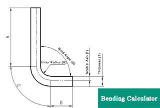
0° – 180° Bend Allowance Chart for Sheet Metal Bending
Have you ever wondered how sheet metal parts are designed and manufactured with precision? In this blog post, we'll dive into the fascinating world of bend allowance - a crucial…
Ever wondered why your sheet metal projects sometimes bend awkwardly or crack? This article demystifies the crucial role of fabrication holes in sheet metal bending. You’ll learn how these holes prevent drawing and ensure smoother bends, the techniques for determining their optimal size and shape, and methods for improving hole placement to avoid material loss and enhance weld quality. By the end, you’ll have practical insights to enhance your sheet metal fabrication skills and achieve flawless results.
The sheet metal fabrication hole is designed to prevent drawing during sheet metal bending.
When the bending line intersects at a single point or is close to the edge of the sheet metal and less than twice the thickness of the plate, it is necessary to increase the size of the fabrication hole to prevent bending and drawing.
Fabrication holes are typically used in sheet metal parts that require edge wrapping and bending. In cases where edge wrapping and bending are not required, the need for a starting fabrication hole can be eliminated.
Disadvantages of not having fabrication holes:
Without fabrication holes, the edges and corners of the material will have a reduced thickness and will require filler for welding. This can also result in welding deformation.
Advantages of having fabrication holes:
In cases of edge wrapping, fabrication holes can ensure a smooth bend in the wrapped edge without bending or drawing.
Determining the size of the fabrication hole:
The size of the sheet metal fabrication hole is determined based on its position. If the hole is located at the intersection of two lines, it should be twice the thickness of the plate. The minimum thickness should not be less than 1.5 times the thickness of the sheet metal. When bending thick sheets, the fabrication hole should be appropriately enlarged to account for the bending fillet.
Disadvantages of this fabrication hole:
After bending, especially for thick plates, there is significant material loss at the bending angle, making it unsightly and difficult to weld. In this situation, it is necessary to improve the fabrication hole manufacturing method.
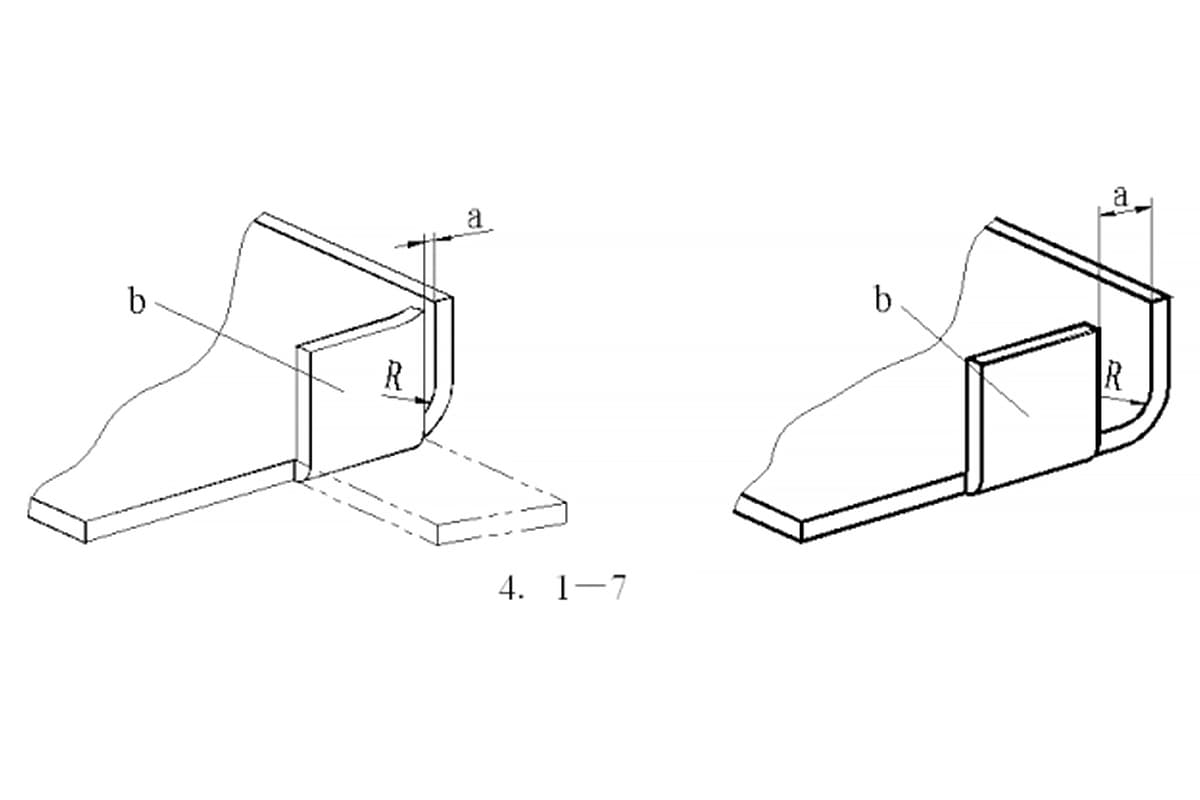
The size of the hole in sheet metal fabrication can be determined based on the bending edge and taking into account the plate thickness and bending fillet to avoid any potential issues.
For a visual representation, please refer to the figure below.
The figure above illustrates a square sheet metal box with a thickness of 3mm and a bending height of 15mm on all four sides.
Improvement in Blanking Method:
There are two methods of sheet metal blanking, namely punch blanking and laser cutting blanking. Punch blanking results in primarily round holes, with limited ability to produce square or long holes due to mold restrictions. In the case of the 3mm sheet metal shown in the figure above, laser cutting is used for blanking.
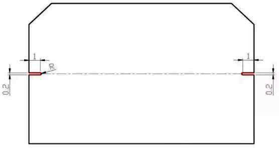
Improvement in Fabrication Hole Shape:
To avoid aesthetic issues after bending, a long strip shape can be used for the fabrication holes.
Determining the Size of the Long Strip Fabrication Hole:
A width of 1mm is typically used, as it does not negatively impact the appearance or release of sheet metal bending deformations.
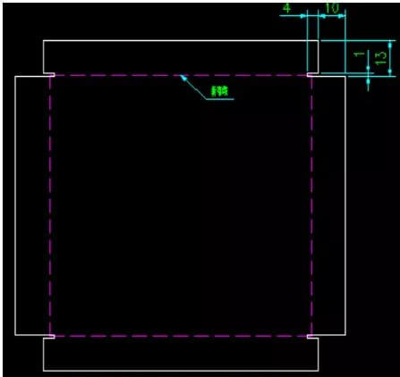
Method for Calculating the Depth Dimension:
The depth dimension is calculated as follows: 10mm is equal to the bending height minus 3mm plus a factor of 5, and 4mm is equal to the thickness of the sheet metal material plus 1mm.
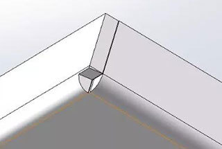
By using this method, the sheet metal part after bending will have a narrow gap of only 1mm. Please refer to the three-dimensional rendering for a visual representation.

After bending the fabrication hole made using this method, the bending angle is well controlled and, as a result, welding can be performed without the need for additional filler material.
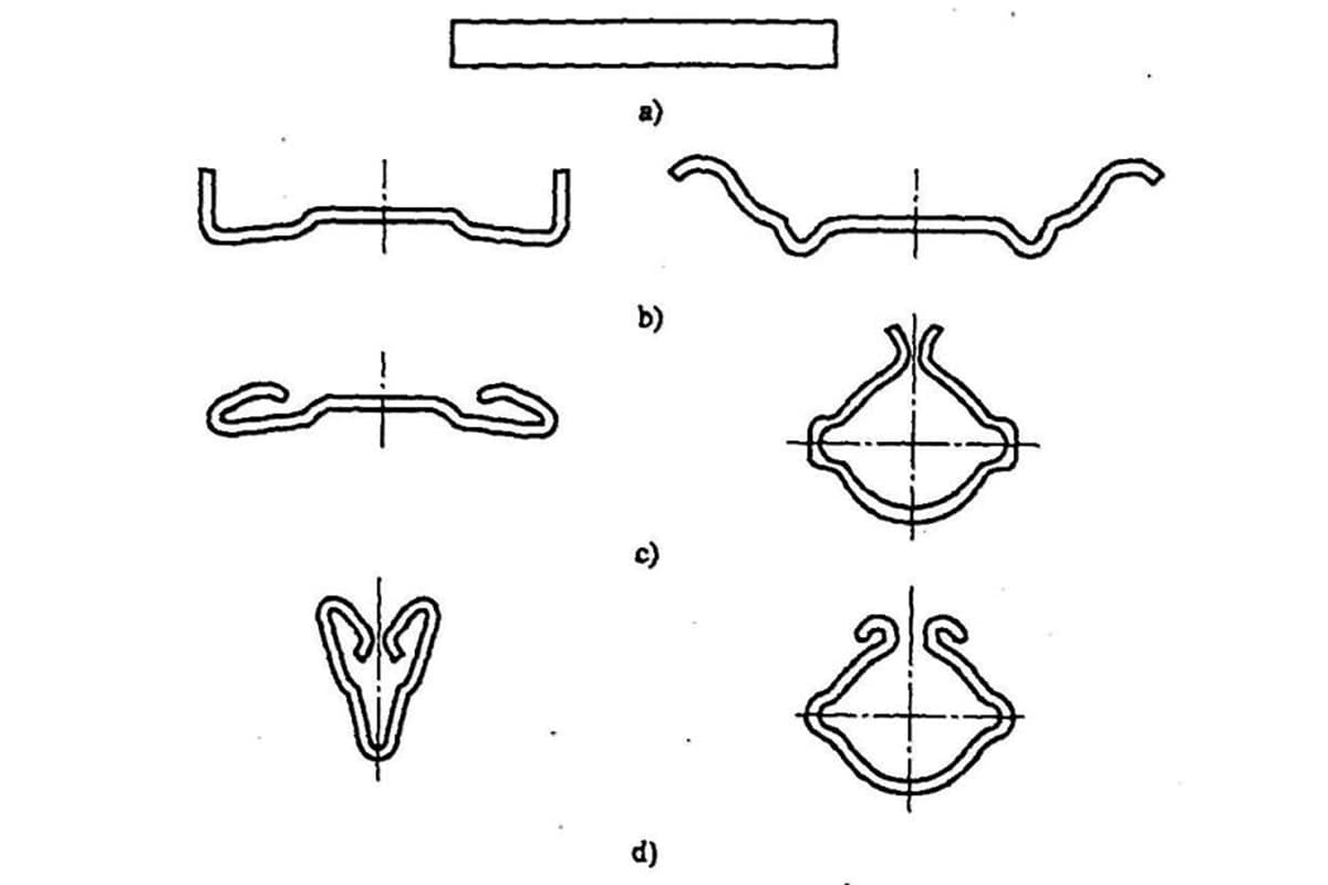
Impact of Bending and Pulling:
(1) Bending Size is Affected:
During the drawing process, a significant amount of force is required to separate the thickness of the sheet metal. This can cause the workpiece to move and result in dimensional displacement because of the unpredictable direction of the applied force.
(2) Bending Die is Vulnerable to Damage:
As previously stated, high levels of force are present at sharp corners, which can surpass the bearing capacity of the die, causing it to collapse and become damaged.
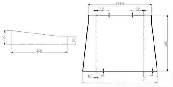
Size and form of fabrication hole:

Scope of use:
The bending angle is not a perfect 90 degrees, and positioning holes are drilled at all bending positions, including at overlapping bending points.

For appearance parts or butt joint parts with stringent accuracy requirements, positioning holes must be drilled at the bending position.

When the bending size exceeds 200mm, all positioning holes must be drilled at the bending position.

For the continuous bending of complex parts, positioning holes should be added starting from the third bending edge.

For parts that cannot be processed following the standard bending sequence, positioning holes must be drilled at the bending position.

Due to limitations in bending equipment, positioning holes must be drilled at all bending positions for parts that require repeated bending.

Positioning holes must be drilled at all bending positions for parts that cannot be butted against the stop ruler type.
Positioning holes must be drilled at the bending position for parts of the guide rail type.

Positioning holes are drilled at the starting points of the arcs at both ends of the curve.

The positioning holes must be drilled at the bend location of the pull plate components.

Positioning holes must be drilled at the overlap location of overlapping components. The positioning hole must be drilled at the specified dimension for continuous bending, based on the overlap edge.


As the founder of MachineMFG, I have dedicated over a decade of my career to the metalworking industry. My extensive experience has allowed me to become an expert in the fields of sheet metal fabrication, machining, mechanical engineering, and machine tools for metals. I am constantly thinking, reading, and writing about these subjects, constantly striving to stay at the forefront of my field. Let my knowledge and expertise be an asset to your business.