Welded structures often have shortcomings that are mainly reflected in the problems of welded joints. These problems include the following aspects:
- The welding process involves uneven heating and cooling, which results in welding residual stress and distortion. These issues not only affect the overall dimensions and appearance quality of the welding structure, but also create difficulties for continuous processing after welding. In some cases, the strength of the welding structure may also be directly affected.
- Welded joints go through three stages: smelting, solidification, and heat treatment.
- Welding can change certain properties of the material.
Welding stress and distortion
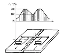
Local high-temperature heating during welding results in an uneven temperature distribution on the weldment, which in turn causes welding stress and distortion in the welding structure.
Welding stress is the primary cause of brittle fracture, fatigue fracture, stress corrosion fracture, and instability failure.
Welding distortion affects the shape and dimensional accuracy of the structure, making it difficult to meet technical requirements. This directly impacts the manufacturing quality and service performance of the structure.
Generation of welding stress and distortion
1. Basic knowledge of welding stress and distortion
1. Distortion
The shape and size of an object change under the action of external force or temperature
2. Stress
The interaction force within an object caused by external forces or other factors is called internal force. The internal force per unit cross-sectional area of an object is called stress.
3. Welding stress and welding distortion
Welding stress is the internal stress that exists in the weldment during and after the welding process.
The change in weldment size caused by welding is called welding distortion.
2. Causes of welding stress and distortion
1. Uneven heating of weldments
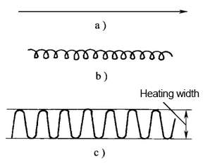
(1) Stress and distortion caused by central heating of long strip (similar to surfacing)
Stress and distortion of steel strip center during heating and cooling
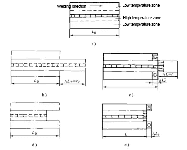
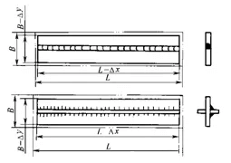
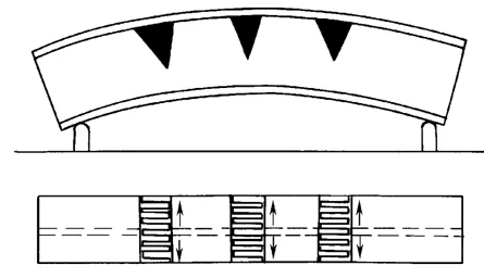
(2) Stress and distortion caused by heating on one side of the long strip (equivalent to plate edge surfacing)
Stress and distortion during heating and cooling on one side of steel plate edge
2. Shrinkage of welded metal
3. Change of metal structure
4. Rigidity and restraint of weldment
Welding distortion
1. Types of welding distortion and its influencing factors
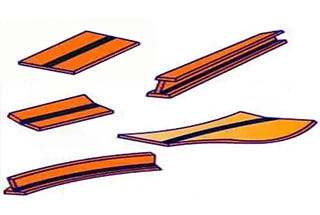
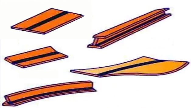
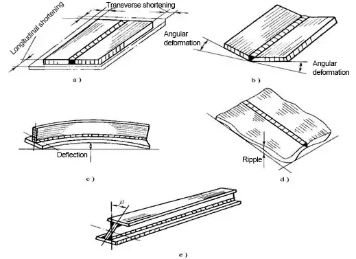
Welding distortion can be divided into five basic forms: shrinkage distortion, angular distortion, bending distortion, wave distortion and deformation distortion.
Basic forms of welding distortion
1). Shrinkage distortion
The phenomenon that the size of weldment is shorter than that before welding is called shrinkage distortion.
Longitudinal and transverse shrinkage distortion
(1) Longitudinal shrinkage distortion
(2) Transverse shrinkage distortion
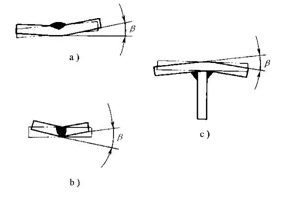
2). Angular distortion
The root cause of angular distortion is the uneven distribution of transverse shrinkage along the plate thickness.
Angular distortion of several joints
Angular distortion of T-joint
3). Bending distortion
Bending distortion is caused by the non-coincidence or asymmetry between the centerline of the weld and the neutral axis of the structural section, as well as the uneven distribution of the shrinkage of the weld along the width of the weldment.
(1) Bending distortion caused by longitudinal shrinkage
Bending distortion caused by longitudinal shrinkage of weld
(2) Bending distortion caused by transverse shrinkage
Bending distortion caused by transverse shrinkage of the weld
4). Wave distortion
Wave distortion often occurs in the welding process of thin plates with a thickness of less than 6mm, which is also called instability distortion.
Wave distortion caused by weld fillet distortion
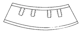
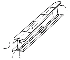
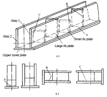
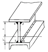
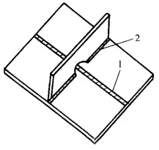
5). Distortion
The main cause of distortion is the uneven distribution of weld fillet distortion along the weld length.
Distortion of I-beam
2. Measures to control welding distortion
1). Design measures
(1) Select a reasonable weld shape and size
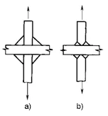
1) Select the smallest weld size.
Cross joint with the same bearing capacity
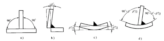
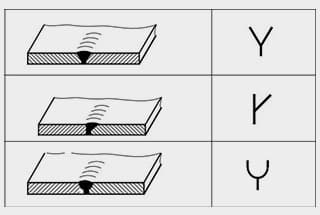
2) Select a reasonable groove form.
Groove of T-joint
(2) Reduce the number of welds
Profiles and stamping parts are the preferred options when possible. For structures with many and dense welds, cast weld joint structures can be used to reduce the number of welds. Additionally, increasing the thickness of the wall plate to reduce the number of ribs, or using profiled structures instead of rib structures, can help prevent distortion of thin plate structures.
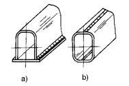
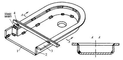
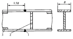
(3) Reasonable arrangement of weld position
Beam, column and other welded components often have bending distortion due to the eccentric configuration of the weld.
Weld arrangement of the box structure
Reasonably arrange the weld position to prevent distortion
2). Process measures
(1) Allowance method
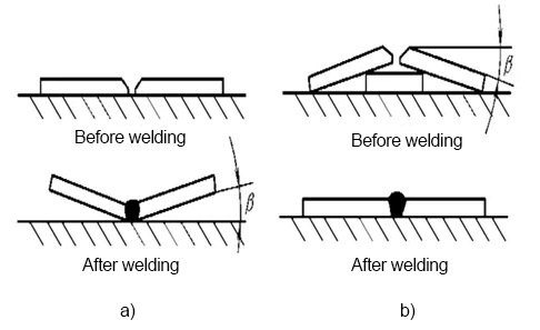
(2) Inverse distortion method
Inverse distortion method for flat plate butt welding
(3) Rigid fixation method
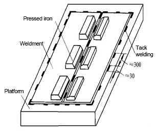
1) Fix the weldment on the rigid platform.
Rigid fixation during thin plate splicing
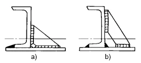
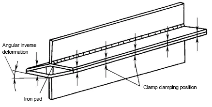
2) The weldment is combined into a more rigid or symmetrical structure.
Rigid fixation and anti-distortion of T-beam
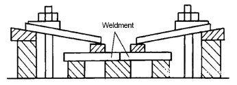
3) The welding fixture is used to increase the rigidity and restraint of the structure.
Rigid fixation during butt splicing
4) Use temporary supports to increase the restraint of the structure.
Temporary support during shield welding
(4) Select a reasonable assembly and welding sequence.
The assembly welding sequence has a great influence on the distortion of the welded structure.
(1) If conditions permit, large and complex welded structures should be divided into several parts with simple structures, welded separately, and then assembled as a whole.
(2) The weld when welding should be close to the neutral axis of the structural section as much as possible.
Assembly and welding of the main beam
3) For the structure with the asymmetric arrangement of welds, the side with few welds shall be welded first during assembly welding.
Welding sequence of upper die of press
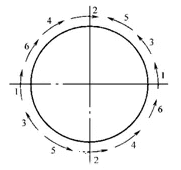
4) The structure with a symmetrical arrangement of welds shall be welded symmetrically by even welders.
Welding sequence of cylinder butt weld
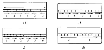
5) When welding long welds (more than 1m), the direction and sequence shown in the figure below can be used to reduce the shrinkage distortion after welding.
(5) Reasonably select welding methods and welding process parameters
Welding of asymmetric section structure
(6) Heat balance method
Use the heat balance method to prevent welding distortion
(7) Heat dissipation method
3. Method for correcting welding distortion
1). Manual correction
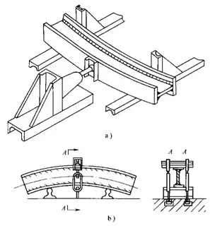
2). Mechanical correction method
Correction of bending distortion of the beam by the mechanical correction method
3). Flame heating correction method
The ways of flame heating include point heating, linear heating and triangular heating.
(1) Spot heating
(2) Linear heating
(3) Triangular heating
Flame correction of bending distortion of I-beam
The correction of welding distortion by flame heating depends on the following three factors:
(1) Heating mode
(2) Heating position
(3) Heating temperature and area of the heating zone
Welding residual stress
1. Classification of welding residual stress
1). According to the causes of stress
(1) Thermal stress
(2) Corresponding stress
(3) Plastic strain stress
2). According to the time of stress existence
(1) Welding instantaneous stress
(2) Welding residual stress
2. Distribution of welding residual stress
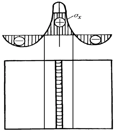
1). Distribution of longitudinal residual stress σx
Distribution of butt joint on weld 0x cross section
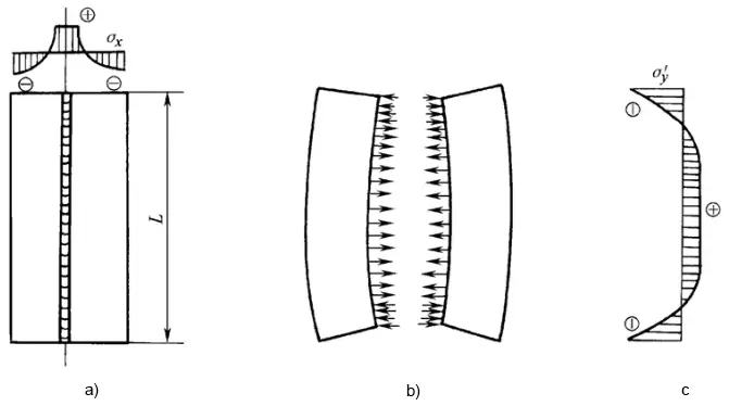
2). Distribution of transverse residual stress σy
(1) The transverse stress caused by longitudinal shrinkage of welding and its adjacent plastic distortion zone is σ’y
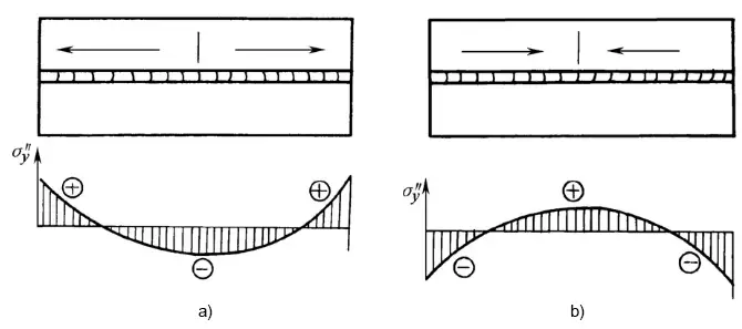
(2) Mechanical stress caused by transverse shrinkage year σ” y
Distribution of σ” Y during welding in different directions
3. Influence of welding residual stress on welding structure
1). Impact on structural strength
2). Influence on the dimensional accuracy of weldment processing
Internal stress release and distortion caused by machining
3). Influence on the stability of compression members
4. Measures to control welding residual stress
1). Design measures
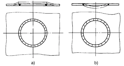
1) Minimize the number and size of welds on the structure.
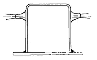
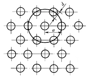
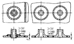
2) Avoid excessive concentration of welds, and keep sufficient distance between welds.
Welding of vessel nozzle
3) The joint form with less rigidity shall be adopted.
Measures to reduce the rigidity of joints
2). Process measures
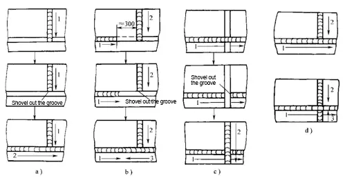
1) Adopt reasonable assembly welding sequence and direction.
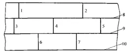
① When welding the weld on a plane, it shall be ensured that the longitudinal and transverse shrinkage of the weld can be relatively free.
Reasonable assembly and welding sequence of splicing welds
② The weld with the largest shrinkage shall be welded first.
Welding sequence of duplex beam structure with cover plate
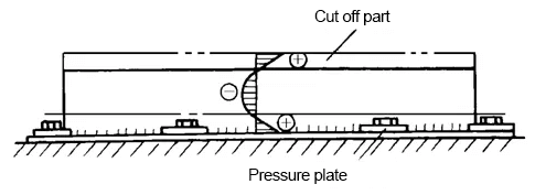
③ The weld with the largest stress during operation shall be welded first.
Welding sequence of butt I-beam
④ When the plane cross weld is welded, it is easy to produce large welding stress at the intersection of the weld.
Welding sequence of plane cross welds
⑤ The structure where butt welds and fillet welds intersect.
2) Preheating method.
3) Cold welding.
4) Reduce the restraint of welds.
Reduce local stiffness and internal stress
Schematic diagram of heating “stress relief zone” method
5. Method for eliminating or reducing welding residual stress
1). Heat treatment method
(1) Integral heat treatment
(2) Local heat treatment
2). Mechanical stretching method
3). Temperature difference stretching method
Schematic diagram of eliminating residual stress by “temperature difference tensile method”
4). Hammer weld
5). Vibration method
6. Determination of welding residual stress
1). Mechanical method
(1) Slitting method
(2) Drilling method
2). Physical methods
(1) Magnetic method
(2) X-ray diffraction
(3) Ultrasonic method