Press Brake Operation Manual (Training PDF)
Attention all mechanics and engineering enthusiasts! Have you ever wondered about the ins and outs of operating a press brake machine? In this blog post, we'll dive into the world…
Ever wondered how a press brake achieves such precise bends? This article explores the fascinating world of press brake axes, revealing the secrets behind their roles and functions. Learn how mastering these axes can elevate your metalwork to new levels of accuracy and efficiency. Get ready to uncover the mechanics that make perfect bends possible!
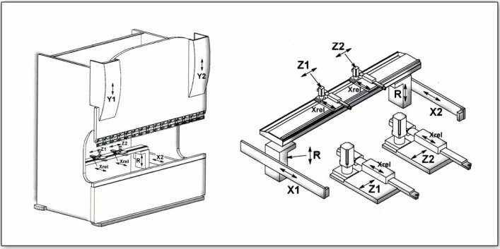
In the world of press brakes, understanding the various axes involved in the operation of the machine is crucial for both efficiency and precision. Each axis serves a specific purpose and is named using a letter or number, such as X, R, V, Y1, Y2, Z1, and Z2.
To effectively utilize a press brake, operators need to have a clear grasp of the functions and roles of these axes.
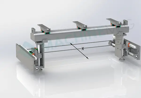
The X-axis is responsible for the movement of the back gauge, primarily its horizontal positioning. This axis ensures that the workpiece is aligned correctly and contributes to the overall accuracy of the bending process. Adjusting the X-axis enables the operator to control the bend length and position the workpiece for consistent and precise bends.
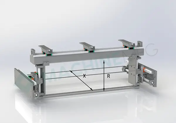
Meanwhile, the R-axis refers to the vertical movement of the back gauge. By adjusting the R-axis, operators can control the bending height, allowing for variation in the workpiece’s thickness or the desired angle of the bend. This axis is integral in managing the depth of the bend and creating consistent, accurate, and repeatable results.
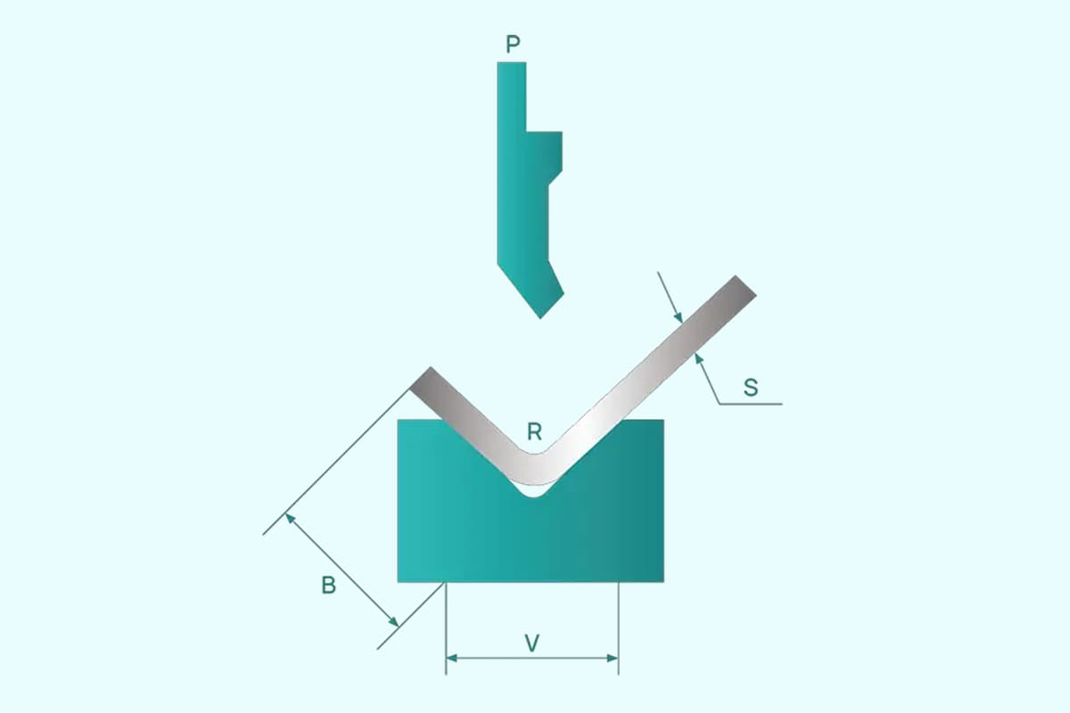
The V-axis is associated with the die opening, which is crucial for determining the appropriate bending force. By adjusting the V-axis and selecting the correct die width, the press brake can exert the proper force on the workpiece, ensuring clean, precise bends and minimizing the risk of damage or imperfections.
The Y1 and Y2 axes control the lowering of the press brake’s top beam during the bending process. Both Y1 and Y2 axes work independently of each other, allowing for a more refined and synchronized operation that ensures precision and repeatability in the bends. By fine-tuning the Y1 and Y2 axes, operators can achieve the desired bending angles and maintain consistency across multiple bends.
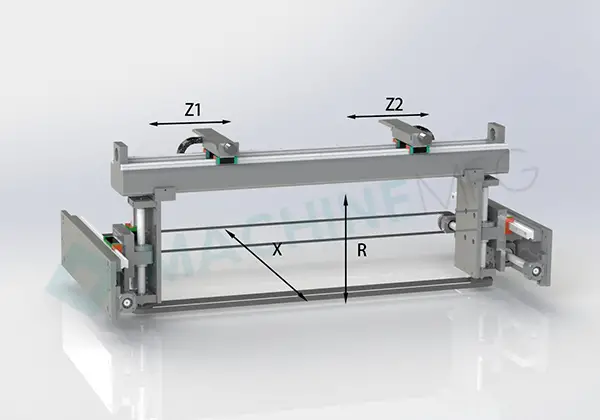
Lastly, the Z1 and Z2 axes manage the horizontal movement of the back gauge fingers on either side of the machine. This allows for better control and flexibility when positioning the workpiece, enabling operators to account for different bend lengths and workpiece sizes. Adjusting the Z1 and Z2 axes ensures the workpiece is accurately positioned for each bend, contributing to overall precision and efficiency.
By understanding the functions and roles of these axes, operators can not only improve their efficiency but also significantly increase the quality and consistency of the bends they produce using a press brake. With proper knowledge and adjustment of these axes, press brake operation becomes a more precise and controlled process.
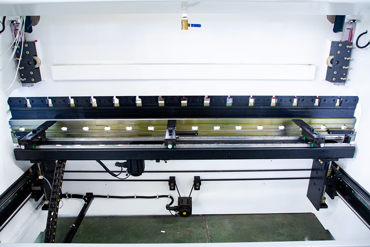
The press brake axis can be simply defined as the motion and functional components controlled by the controller in the press brake machine. It is often referred to as the press brake axis for short.
In general, the press brake axis is named according to the position where the spatial position of each axis in the machine conforms to the coordinate system.
However, some other motions and functional components are named according to conventional usage or international customary standards.
A CNC press brake machine is typically equipped with several axes, which are configured according to the process requirements of the user’s workpiece.
The functions defined by each press brake axis are as follows:
There are several types of axis in a CNC press brake:
Among the above-mentioned axes, Y1, Y2, and V are necessary for every CNC press brake, while the back gauge and servo-following material support axes can be optionally selected by users according to the needs of the processed parts.
When selecting the back gauge, it should be noted that the X’ axis cannot be selected alone and must be used in conjunction with the Z1 and Z2 axes to have practical significance.
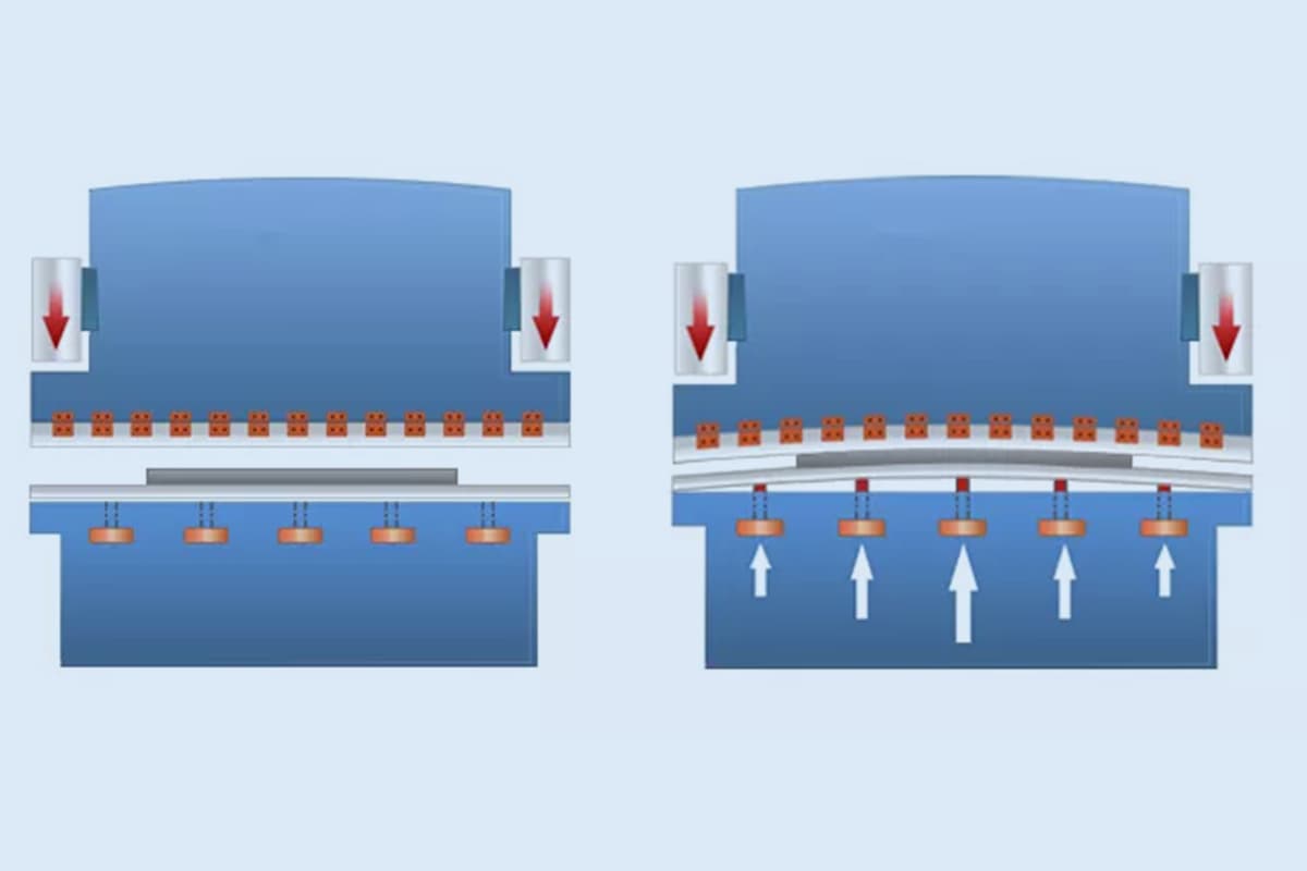
The V-axis is the deflection compensation axis, and there are currently two implementation methods:
One is position control, which gives an equal amount of anti-deformation at the corresponding point based on the deflection deformation curve of the worktable during bending to compensate for the elastic deflection deformation of the machine tool during bending loading;
The other is pressure control, which adjusts the pressure of multiple deflection compensation cylinders according to the bending force so that the resistance to the bending force is generated at multiple points on the standing plate of the worktable to prevent deflection deformation.
As far as the actual deflection deformation curve is concerned, the first method is superior and can achieve higher bending accuracy.
The accuracy of the Y1, Y2, and V axes plays an important role in the angle and straightness of the processed parts. It is worth noting that for thin sheets (less than 3mm), the quality of the sheet itself, such as the size of thickness errors, uniformity of the material, and direction of rolling texture, directly determines the accuracy of the bent parts!
First of all, it is essential to note that the “+1” axis refers to the press brake crowning axis, which is the V axis. The Y1 and Y2 axes control the up and down movement of the left and right oil cylinders separately.
Therefore, it is easy to understand the 3+1, 4+1, 6+1, and 8+1 axes, and their details are as follows:
Y1-The Y1-axis refers to the vertical movement of the left side of the upper die relative to the work surface. This axis is responsible for controlling the height of the left side of the upper die as it moves up and down.
Y2-The Y2-axis refers to the vertical movement of the right side of the upper die relative to the work surface. This axis is responsible for controlling the height of the right side of the upper die as it moves up and down.
X-The X-axis refers to the horizontal movement of the back gauge relative to the center of the lower die. The X-axis controls the position of the back gauge as it moves towards and away from the lower die.
V-The V-axis controls the vertical movement of the lower die relative to the work surface. This axis controls the height of the lower die as it moves up and down.
Y1-The Y1-axis refers to the vertical movement of the left side of the upper die relative to the work surface. This axis is responsible for controlling the height of the left side of the upper die as it moves up and down.
Y2-The Y2-axis refers to the vertical movement of the right side of the upper die relative to the work surface. This axis is responsible for controlling the height of the right side of the upper die as it moves up and down.
X-The X-axis refers to the horizontal movement of the back gauge relative to the center of the lower die. The X-axis controls the position of the back gauge as it moves towards and away from the lower die.
R-The R-axis refers to the vertical movement of the back gauge relative to the lower die surface. The R-axis controls the height of the back gauge as it moves up and down.
Z1-The Z1-axis controls the movement of the left side of the back gauge from left to right.
Z2-The Z2-axis controls the movement of the right side of the back gauge from right to left.
V-The V-axis controls the vertical movement of the lower die relative to the work surface. This axis controls the height of the lower die as it moves up and down.
Y1-The Y1-axis refers to the vertical movement of the left side of the upper die relative to the work surface. This axis is responsible for controlling the height of the left side of the upper die as it moves up and down.
Y2-The Y2-axis refers to the vertical movement of the right side of the upper die relative to the work surface. This axis is responsible for controlling the height of the right side of the upper die as it moves up and down.
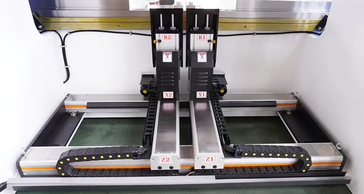
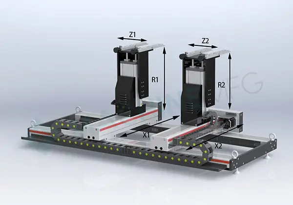
X1-The X1-axis refers to the horizontal movement of the left side of the back gauge away from the lower die. This axis controls the distance between the back gauge and the lower die.
X2-The X1-axis refers to the horizontal movement of the right side of the back gauge away from the lower die. This axis controls the distance between the back gauge and the lower die.
R1-The R1-axis refers to the vertical movement of the left back gauge relative to the lower die surface. This axis controls the height of the back gauge as it moves up.
R2-The R2-axis refers to the vertical movement of the right back gauge relative to the lower die surface. This axis controls the height of the back gauge as it moves down.
Z1-The Z1-axis controls the movement of the left side of the back gauge from left to right.
Z2-The Z2-axis controls the movement of the right side of the back gauge from right to left.
V-The V-axis controls the vertical movement of the lower die relative to the work surface. This axis controls the height of the lower die as it moves up and down.

As the founder of MachineMFG, I have dedicated over a decade of my career to the metalworking industry. My extensive experience has allowed me to become an expert in the fields of sheet metal fabrication, machining, mechanical engineering, and machine tools for metals. I am constantly thinking, reading, and writing about these subjects, constantly striving to stay at the forefront of my field. Let my knowledge and expertise be an asset to your business.