1. Definition and classification of single-sided welding and double-sided forming
1.1 Definition of single side welding and double side forming
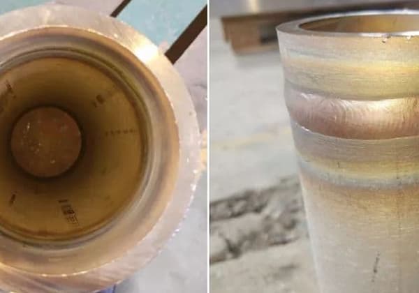
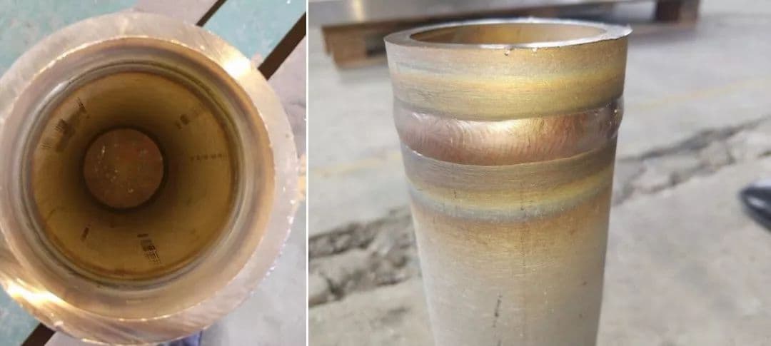
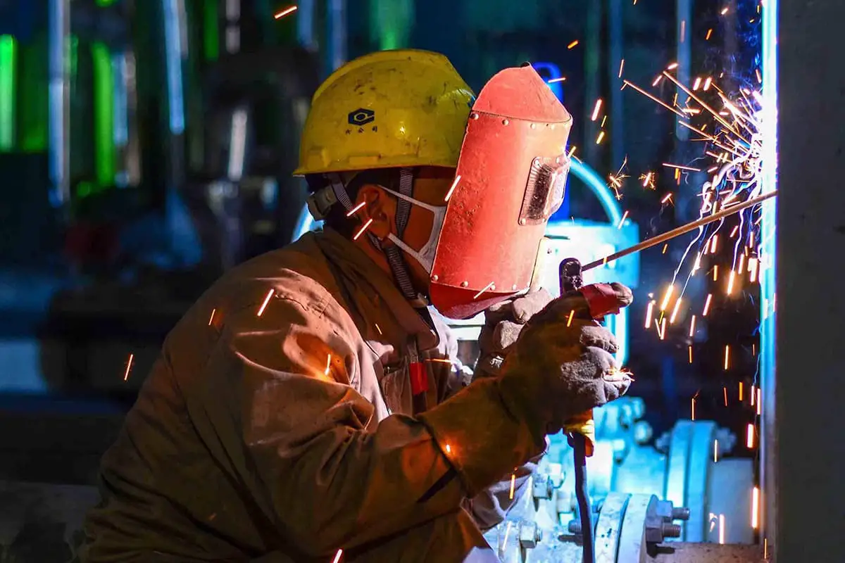
Single-side welding and double-side forming is an essential methods and skills for welders who are engaged in welding pressure vessels, important silos, and boilers. It is also used in manufacturing and installing important welded steel structures that require full penetration but cannot be processed and re-welded on the back of the components.
During such welding, no other auxiliary measures are necessary. However, when positioning welding is required at the root of the groove, different gaps should be reserved according to different welding methods.
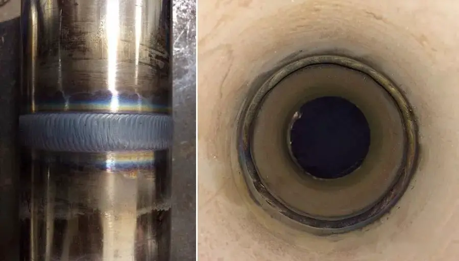
When welding is carried out on the front side of the groove, uniform, regular, and qualified welds can be obtained on both the front and back sides of the groove. This unconventional welding operation is known as “single-sided welding and double-sided forming.”
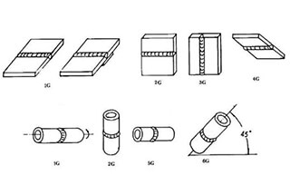
1.2 Grading of single-sided welding and double-sided forming
1.2.1 Arc intermittent welding method
To start the welding process, place the test panel with the small gap end on the left side. Position it for arc striking and use a long arc to preheat the welding components for a certain amount of time. Then, press down on the arc and swing the electrode laterally between the two blunt edges for welding.
As the molten metal of the blunt edge connects with the molten metal of the electrode, listen for the “porphyrin” sound, which indicates successful bonding. The arc light will then be extinguished.
During each continuous arc, the welding electrode’s center should be aligned to 2/3 of the welding pool. This ensures that both sides of the blunt edge are melted at the same time. Once the “porphyrin” sound is heard, quickly extinguish the arc, allowing the newly formed molten pool to cover about 2/3 of the previously formed molten pool.
1.2.2 Continuous arc welding method
Continuous arc welding is a technology that involves a continuous burning of the arc during welding, without extinguishing the arc light. It uses a small groove gap and a small welding current at the beginning while maintaining short arc continuous welding.
The basic elements of this technology involve striking the arc with the electrode and pressing it to the minimum. Then, at the welding starting point, the sawtooth-shaped electrode moving method with a small pitch is used to swing the electrode laterally to preheat the welding components.
The welding rod should be sent to the root as far as possible to conduct the electrode breakdown action. When a “porphyrin” sound is heard, the weldment will form a dissolved hole. The arc should be immediately transferred to any groove surface position and then a certain electrode angle should be used between the groove surfaces.
The operation involves non-stop small actions that last about 2 seconds. When the arc melts the groove root on both sides for about 1.5mm, the welding rod should be raised by 1-2mm. The electrode should be swung in a zigzag manner with a small pitch so that the arc is in front of the melting hole while welding is carried out forward.
During welding, it’s crucial to ensure that the center of the welding rod is aligned with the front edge of the weld pool and the junction of the base metal so that each new weld pool overlaps with the previously generated weld pool. During arc extinguishing, the electrode should be slowly brought to the right or left side behind the molten pool, and raised to extinguish the arc.
In joint welding, the arc should be ignited at a distance of 10-15mm away from the crater at the beginning, and the electrode should be moved to half of the crater at a normal speed. The electrode should then be pressed downward, and when a “porphyrin” sound is heard, a slight swing for 1-2 seconds should be made. After that, the electrode should be raised by 1-2mm so that it can be moved forward to weld while melting the front of the melt hole.
2. Process analysis of plate butt welding and double-sided forming
2.1 Preparation before welding
(1) Plate thickness: 12mm, Specification: 300 × 200mm.
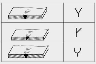
Cut the plate using oxygen and acetylene gas, or use plate shears and cutting machines, and then use mechanical methods such as planers or angle grinders to process V-shaped grooves.
No chamfers are allowed on the back of the grooves.
Ensure that the grooves are straight, smooth, and free of burrs, bulges, and other imperfections.
(2) To clean the test panel, use a file to remove the sharp corners of the groove, keeping the blunt edge size at 0.5-1.0mm. Remove rust, oil, oxides, and other contaminants from the groove and within 20mm on both sides, leaving a metallic luster.
(3) Assembly and tack welding of the test panel.
Perform tack welding on both ends of the back of the test plate, and reserve a shrinkage allowance.
Set the weld end gap at 3.0-3.5mm, the final weld end at 3.5-4.0mm, and the positioned weld length at about 10-15mm.
Ensure that the positioned weld is firm, especially at the final weld end.
To avoid any negative impact on continuous welding or fracture during welding caused by groove gap reduction in the non-welded section due to weld shrinkage, reserve a reverse deformation allowance during positioned welding, i.e., a reverse deformation of the angle of 3 °-4 °.
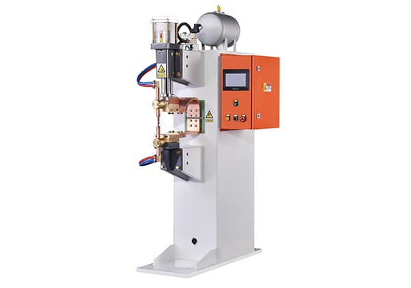
(4) Welding equipment: ZXG series DC arc welding machine.
Type and polarity of the power supply: Ensure that the DC welding rod is not affected by dampness and deterioration, the welding core is free of rust, and the coating does not crack or fall off.
Bake the welding rod to 350-400℃ before use, maintain a constant temperature for 2h, and weld in four layers.
(5) Fix the test plate: Place the anti-deformed test plate horizontally on the welding frame at an appropriate height.
The welder should not sit down during welding and must operate in a squatting position.
The groove angle of the test plate is 60°.
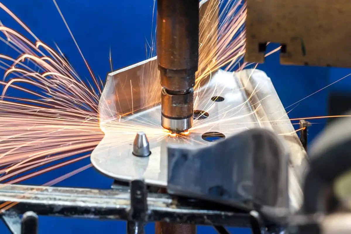
2.2 Welding operation
2.2.1 Welding of bottom layer
Primer welding can be carried out using either general welding or end arc welding, or continuous arc welding.
To begin the welding process, the arc should be ignited on the inner side of the groove of the test panel, and the bottom arc should be pressed. The welding rod should be swung slightly back and forth between the two blunt edges of the groove until the molten iron at the edge combines with the molten droplet of the welding rod, producing a “porphyrin” sound and forming the first molten pool.
At this stage, there should be a dissolution hole in front of the dissolution tank that is 0.5-1.0mm deep on both sides of the test plate groove.
The zigzag or crescent-shaped transverse swing welding method is adopted for the welding rod operation. The length of the swing arc should be less than or equal to the electrode diameter. A short arc is used to send the molten iron through the root of the groove to the back of the weldment.
When the welding rod is transported to both sides of the groove, a 1-2s pause is required. This pause is conducive to good fusion of the filler metal and the base metal, and it also prevents the formation of sharp corners at the junction of the weld and the groove, which is helpful for slag removal.
2.2.2 Electrode angle
The included angle of the welding forward direction is 70 °-80 °.
A proper electrode angle is conducive to separating the molten slag from the molten iron, keeping the molten pool clear and bright all the time, and avoiding clamping.
Main points of welding rod: look, listen, be accurate and short.
The included angle for the forward welding direction should be between 70° to 80°.
A proper electrode angle helps to separate the molten slag from the molten iron, keeps the molten pool clear and bright, and prevents clamping.
The main points for using a welding rod are: to observe, listen, be accurate, and work efficiently.
“Observe” means to pay attention to the shape of the molten pool and the size of the melting hole, which determines the height and reinforcement of the back weld.
The molten pool should be round or oval in shape and always bright and clear to separate the slag from the molten iron.
The melting hole should be such that the arc melts all the blunt edges on both sides and penetrates 0.5 to 1.0 mm into the base metal on each side.
When the hole is too large, the weld on the back becomes too high, and in severe cases, weld beading or burn-through can occur.
To remedy this, the welding speed should be increased, the swing range of the electrode towards both sides of the groove should be increased, and the included angle between the electrode and the welding direction should be reduced.
When the hole is too small, the root of the groove is not fully welded, and the fusion of the weld root is not good.
To address this, the bottom arc should be pressed to increase the angle of the welding rod in the forward direction, slow down the welding speed and swing amplitude, reduce the angle between the welding rod and the forward direction of welding, and maintain the shape of the weld pool and the size of the melting hole.
During welding, it is essential to control the flow direction of molten iron and solution.
The electric arc should always burn in front of the molten iron.
The reverse blowing force of the gas generated by the electric arc and coating melting is used to blow the molten iron to the rear of the molten pool, ensuring weld penetration, separation of molten slag and iron, and reducing the possible defects of slag inclusion and porosity.
Additionally, it is necessary to observe the fusion of the welded groove at all times.
The rear edge of the molten pool should be completely fused with the grooves on both sides.
“Listen” means the welder should not be distracted during welding and should listen to the “porphyrin” sound when the arc breaks through the test plate.
If this sound is not heard, the groove root is not broken down by the arc, and continuing to weld forward will result in an impermeable weld.
Generally, keep the end of the electrode 2 or 3 mm away from the groove root.
“Accurate” means the arc contact position should be precise. Each new molten pool should overlap the previous one by 2/3 to ensure that 1/3 of the arc is directly in front of the molten pool.
When the welder hears the “por por” sound, they should quickly extinguish the arc behind the molten pool. This way, the protective effect of the arc on the molten pool can be fully exerted, preventing the formation of pores.
Short” refers to the time for arc extinguishing and butt welding, which should be completed as quickly as possible; otherwise, cold shrinkage defects may occur, and metal cracking can result due to insufficient fusion between molten pools.
To avoid cold shrinkage holes, increase the arc extinguishing frequency and reduce the arc contact time. While the previous molten pool is still liquid, the next molten pool should already be formed, so that the molten pool remains in a high-temperature state.
For the two-point breakdown method, the arc extinguishing frequency should be 50 to 60 times per minute, while for the single-click breakdown method, the arc extinguishing frequency should be around 80 times per minute.
2.2.3 Joints
The different types of joints are categorized as hot connections and cold connections, and their descriptions are provided separately below.
Hot connection:
To weld in the hot state of the arc crater, ignite the arc on the slope, 10-15 seconds behind the crater. Weld towards the front arc stop to gradually raise the temperature at the bottom of the crater. Then, press the electrode down along the pre-molten hole. Once you hear the sound of “porphyrin”, stop and lift the electrode for normal welding.
It’s better to replace the electrode sooner rather than later.
Cold connection:
When the arc crater has cooled down, remove the arc crater and the first 10mm of molten slag from the carbon steel. Clean the area and then replace the welding rod.
At the lowest point of the slope, quickly press the welding rod down along the pre-molten hole. Once you hear the sound of “porphyrin”, pause for about 1 second before raising the welding rod to start normal welding.
There are two methods for the arc break welding technique: the one-click and two-click piercing techniques.
For the two-click piercing technique, the arc is ignited on both sides of the groove, and a drop of molten iron is dropped on the left blunt edge first, followed by a drop of molten iron on the right blunt edge, gradually reciprocating.
This welding technique is suitable for work with large welding assembly clearance.
For the one-click penetration method, the arc ignites the blunt edges on both sides of the groove and melts simultaneously.
The basic mode of operation is as follows: ignite the arc.
During welding, start by striking an arc at the inner side of the groove on the starting end of the test panel. Preheat the starting part with a long arc, then lower the arc and swing the electrode back and forth between the two blunt edges.
When the molten iron at the blunt edge of the groove combines with the metal droplet of the electrode and a sound of “porphyrin” is heard, the first molten pool will be formed and the arc will extinguish.
At this point, the front end of the first molten pool will become a molten hole, which should be made 0.5-1.0mm deep on both sides of the test plate. Replace the welding rod joint.
The method for changing the welding rod during arc break welding is basically the same as continuous arc welding. Before changing the welding rod, to prevent cold shrinkage holes due to arc extinguishing, the arc should not be extinguished too quickly. Two or three drops of molten iron should be sent to the edge or north of the weld pool quickly in advance, the back weld pool should be filled, and the temperature of the weld pool should be controlled to cool it slowly.
A weld hole should be formed in front of the weld pool. Press down the arc to one side of the groove, and weld back about 10mm before extinguishing the arc. This ensures that the molten iron in the rear molten pool is full and sufficient to prevent cold shrinkage defects.
After the rapid electrode change, the arc should be started within 10-15mm of the front of the crater. Once ignited, the arc should be stretched backward, and the metal to be welded should be preheated with a long arc.
Then, the arc should be pressed down about 10mm behind the crater. The welding rod should be operated continuously to the root of the crater.
After hearing the “porphyrin” sound, the arc should be stopped for about 2 seconds to extinguish it. Then, the original intermittent arc welding method should be used to continue welding.
Please note the following:
(1) The primer’s weld thickness at the front and back of the groove should be between 1.5 and 2.0mm.
(2) Welders should rotate the bar using their wrists in a flexible manner.
(3) Four welds, each 300mm in length, must be completed.
2.2.4 Welding of the filler layer
After the welding slag from the previous layer has cooled down, thoroughly remove any slag and splashes, paying special attention to the corners.
Once the slag has been removed, use a wire brush to clean the area until the metal surface is exposed.
Start the arc 10mm away from the beginning of the weld, and then return the arc to the starting point for welding.
Use a crescent-shaped or sawtooth-shaped electrode, and pause slightly when the electrode swings to either side of the groove to stabilize the arc.
Move quickly through the middle of the groove while keeping the arc as low as possible. This will help facilitate the removal of impurities at the sharp corners of the deep groove and prevent slag inclusion.
Maintain balance in the molten pool and both sides of the groove to prevent the formation of slag inclusion at the junction between the filler metal and the base metal. This is difficult to clear.
The included angle between the welding rod and the welding progress should be 75°-85°.
Adopt a short arc during welding, and ensure that the welding pool is round or oval with consistent shape and size.
Maintain a uniform welding speed and consistent thickness of the welding flesh.
Use thermal methods when welding the joint.
Before changing the welding rod to stop the arc, slightly add molten iron to the formed weld pool.
After a rapid change of the welding rod, ignite the arc about 10mm in front of the arc crater.
Then, pull the arc to 2/3 of the crater, fill the crater first, and then continue with normal welding.
Stagger the connection joints of each layer of the weld.
The filling height of the last layer should be 0.5-2.0mm lower than the surface of the base metal, and the shape should be high on both sides and concave in the middle.
Ensure that the weld is smooth and the groove is excessive to ensure that the groove is clearly visible during the cover welding. This will help ensure that the edge of the cover weld is straight.
2.2.5 Welding of the covering layer
The arc striking method for the capping layer is the same as that for the filling layer. Use a crescent-shaped or transverse sawtooth-shaped electrode.
The swing amplitude of the electrode should be slightly larger than that of the filler layer. Ensure that the swing amplitude is consistent during the swing and the electrode speed is uniform.
The welding pool’s shape is oval. Try to maintain the shape and size of the pool roughly the same, and use short arc welding.
When the welding rod swings to the groove’s edge, stabilize the arc and stop the tip. The fusion at the groove’s edge should be approximately 1.0-2.0mm.
Both sides of the weld’s edges should be well fused to prevent undercutting.
The welding’s forward speed should be uniform to make the weld surface smooth and beautiful.
When using welding rod joints, adopt the hot joint method.
Before replacing the welding rod for arc extinguishing, slightly add molten iron to the weld pool.
After replacing the welding rod, ignite the arc about 10mm in front of the crater, then pull the arc back to 2/3 of the crater, fill the crater, and then carry out conventional welding.
If the joint part is deviated, the joint part will be higher. If the joint is deflected, the weld disjoint defect will occur.
3. Common defects of single side welding and double side forming
In summary, the common defects that may occur during the process of plate-to-plate butt joint, single-sided welding, and double-sided forming include: air pockets, incomplete penetration, incomplete fusion, and weld bead formation, among others.
In the following section, we will analyze and break down these potential defects in more detail.
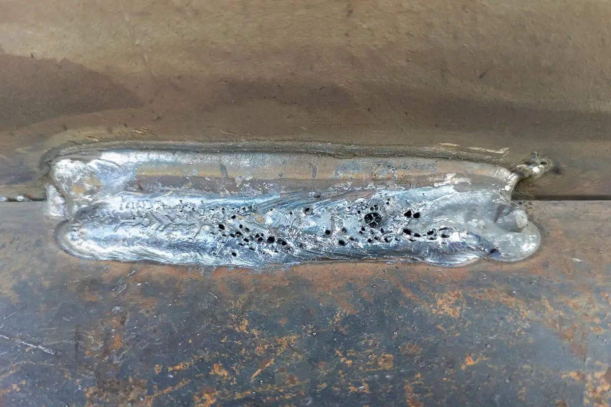
3.1 Porosity
Air holes are formed in the weld metal when gas present in the weld pool fails to escape before the weld metal solidifies during welding.
This gas can be absorbed by the molten pool from the external environment, with hydrogen and carbon monoxide being the most common gases. It may also be produced as a result of the reaction of metal during welding.
For instance, if the base metal contains an excessive amount of sulfur, gas pockets will form during the fusion process with the electrode metal.
(1) The main causes of porosity during welding are analyzed as follows:
The surface of the base metal or filler metal being welded must be clean and free from impurities such as oil stains and rust.
It is important to ensure that the welding flux or electrode is thoroughly dried prior to welding, as the presence of moisture can cause it to decompose into gas during the welding process, leading to an increase in the formation of pores.
Low linear energy during welding results in rapid cooling of the molten pool, which makes it difficult for gas to escape from the weld metal in a timely manner.
Inadequate deoxidation of the weld metal can also lead to an increase in the formation of oxygen pores.
Environmental factors, such as excessive humidity on rainy or foggy days, can cause the weld to absorb moisture from the surrounding air during welding, further increasing the formation of porosity.
(2) Harm of stomata.
There are various specifications that regulate the number of pores allowed.
However, the presence of air holes during welding can decrease the effective sectional area of the weld, loosen the joint, reduce its strength, and result in production accidents, such as leaks.
Porosity can also generate structural defects that cause concentrated stress and damage components, thereby reducing their strength and affecting their service life.
Therefore, it is essential to analyze the causes of pores individually and avoid external factors that can lead to their formation. This approach will help minimize the occurrence of pores during welding.
3.2 Incomplete penetration and fusion
3.2.1 Causes of incomplete penetration
(1) The groove angle of the test plate may be reduced, the blunt edge may be too large, or the assembly gap may be too small, resulting in insufficient spot welding length and a weld that is too thin. Tensile and contraction stresses during welding may cause the gap at the spot welding point to become smaller, or the selected electrode may be too large, preventing the deposited metal from reaching the root of the groove.
(2) Welding speed that is too fast or welding current that is too small may cause decreased arc penetration force, shallow molten pools, and insufficient melting of the edges of the weldment. The arc burning time of breakdown welding on both sides of the groove may also be too short to form a hole of a certain size.
(3) Improper electrode angle or magnetic drift of the arc may cause the heat of the arc to be lost or deviated to one side, resulting in incomplete penetration.
(4) During primer welding, incomplete penetration may occur at the joint. This is a common occurrence in plate weldments after changing the welding rod. The temperature of the striking arc decreases, causing a large temperature difference between the welded and non-welded parts, a large gap between the test plates, and welding is carried out before the required preheating temperature is reached. As a result, the arc at the joint cannot quickly break through the blunt edge of the test piece, causing a section of incomplete penetration at the joint and resulting in defects.
3.2.2 Measures to prevent incomplete penetration defects
(1) Choose the correct electrode angle.
When performing backing welding, it’s important to control the welding speed appropriately to ensure the arc fully melts the root.
(2) Thoroughly clean the groove weld to remove any oil, rust, or other debris.
(3) During the welding process, if the eccentric electrode causes arc deflection, promptly adjust the angle of the electrode. Swing the electrode in the opposite direction of the arc deflection to align the arc with the molten pool or replace the electrode.
(4) Monitor the melting condition closely during welding to ensure proper fusion.
3.3 Overlap
(1) The beveled edge is too blunt and the assembly clearance is too large.
(2) During flat welding, excessive welding current and slow welding speed may cause the weld edge temperature and volume to increase. This can result in liquid metal falling due to gravity.
(3) Improper welding rod angle can also be a problem during welding.
Prevention measures for welding overlap:
(1) Choose the appropriate size for the blunt edge and assembly clearance, and regulate the size of the melting hole during the welding process.
(2) Control the current and interlayer temperature stringently.
(3) Choose an appropriate electrode angle and swing the electrode faster in the middle and slower on both sides.
(4) Observe the state of the molten pool carefully.
(5) If there are more small sparks sprayed from the molten pool, extinguish the arc immediately to lower the temperature of the molten pool before continuing with the welding process.