What if you could ensure your welds are perfect every time? In this article, we’ll explore the welding process evaluation, a crucial method for testing and refining welding techniques. You’ll discover how to prepare, test, and evaluate welds to meet high-quality standards. Whether you’re involved in manufacturing or maintenance, understanding this process can enhance your welding efficiency and product reliability. Dive in to learn the essential steps and benefits of welding process evaluation.
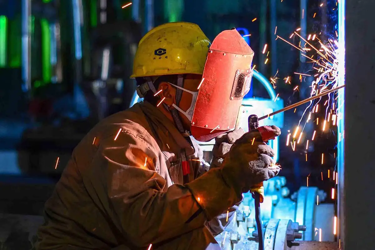
Welding process evaluation is a preliminary preparation for the entire welding operation. It is a process of testing and evaluating the accuracy of the proposed welding process for weldments and related products.
This includes the process of pre-weld preparation, welding, testing, and result evaluation. Welding process evaluation is also an important process in production practice, which has prerequisites, objectives, results, and limited scope.
Therefore, the welding process evaluation involves preparing for welding, welding test pieces, inspecting test pieces, and determining whether the welded joint of the test piece meets all the technical indicators of the required performance according to the proposed welding process.
Finally, all welding process factors, welding data, and test results accumulated throughout the process are organized into conclusive, recommended materials, forming a “welding process evaluation report.”

Welding process evaluation is a critical link to ensure the welding quality of boilers, pressure vessels, and pressure piping. It is an indispensable part of the technical preparation work before the welding of boilers, pressure vessels, and pressure pipes.
It is a mandatory project for the national quality and technical supervision agency to conduct engineering review.
It is a necessary measure to ensure the correctness and rationality of the welding process, and it is an important guarantee to ensure the quality of weldments, and that the performance of the welded joints meets the product technical conditions and corresponding standard requirements.
Therefore, it is necessary to verify the correctness and rationality of the welding process through the corresponding experiment, that is, the welding process evaluation.
Welding process evaluation can also maximize welding production efficiency and minimize production costs under the premise of ensuring the quality of the welded joint, thus achieving the maximum economic benefit.
Compose and issue welding process evaluation assignment – Develop welding process evaluation plan – Weld and inspect test pieces – Prepare welding process evaluation report – Develop welding operation guide (or welding process card) based on the welding process evaluation report.
The main purpose of the assignment is to issue evaluation tasks. Therefore, its main content should include: purpose of evaluation, evaluation indicators, evaluation items, and qualification conditions of departments and personnel responsible for the evaluation tasks.
(1) Determine Evaluation Indicators
Technical indicators are determined based on the theoretical knowledge of regulations and steel (weldability), etc. According to the “Welding Process Evaluation Procedure” DL/T869, the chemical composition and mechanical properties (strength, plasticity, toughness, etc.) of the weld metal should be comparable to or not lower than the lower limit of the parent material.
(2) Determine Evaluation Items
Considering the actual work requirements of the project, cover related items according to the scope of the regulations, and determine the evaluation items. The determination of welding process evaluation items should consider the following aspects:
Steel:
(1) Classification of steel levels;
(2) Basic rules of steel grade levels in “evaluation”;
(3) Division of different types of steel. The meaning of the welding joint of different types of steel is:
The classification of different types of steel welding joints is primarily divided into two categories: one is those with the same metallographic structure but different chemical composition, such as the welding joint between low carbon steel and low alloy steel, both of which belong to the pearlite structure type with minor physical property differences but different chemical composition; the other category is those with different metallographic structures and chemical compositions and significant physical property differences, such as the welding joint between low alloy pearlite steel and high alloy martensitic steel or austenitic stainless steel.
The main feature of different types of steel welding joints is the uneven distribution of chemical composition, metallographic structure, mechanical properties, and welding residual stress. The welding process must address these issues and adopt necessary technological measures to resolve them.
①Type A different steel joints: One side of the welding joint is austenitic steel, and the other is other structured steel. Specific types include: A+M, A+B, A+P, and so on.
②Type M different steel joints: One side of the welding joint is martensitic steel, and the other is other structured steel. Specific types include: M+B, M+P, and so on.
③Type B different steel joints: One side of the welding joint is bainitic steel, and the other is pearlitic copper. There is only one type: B+P.
(1) Butt weld applicable to workpiece thickness
①When the evaluation test piece thickness is 1.5≤δ<8(mm), the range of applicable workpiece thickness is defined as: the lower limit is 1.5mm, the upper limit is 2δ, but not more than 12mm.
②When the evaluation test piece thickness is 8≤δ≤40(mm), the range of applicable workpiece thickness is defined as: the lower limit is 0.75 δ, the upper limit is 1.5δ. When the thickness of the evaluation test piece is more than 40mm, the upper limit is not restricted.
(2) Fillet weld applicable to workpiece thickness
The range of workpiece thickness applicable to the fillet joint thickness δ that has been evaluated is the same as the butt joint thickness, but the test piece thickness is calculated according to the following rules:
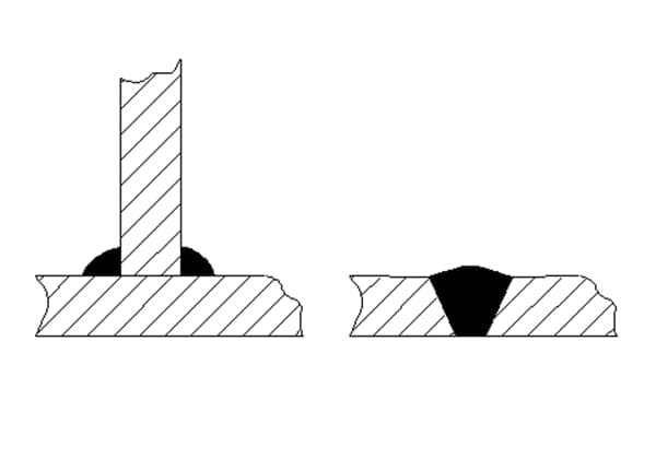
①The thickness of the plate-to-plate fillet weld test piece is the thickness of the web plate.
②The thickness of the tube-to-plate fillet weld test piece is the thickness of the tube wall.
③The thickness of the tube seat fillet weld test piece is the thickness of the branch tube wall.
In addition, for submerged arc welding double-sided welding and small diameter thick-walled, etc., check the regulations carefully and execute according to the regulations.
Each welding method should be assessed individually and cannot replace one another. If a combination of multiple welding methods is used for the “assessment,” each welding method can be “assessed” individually or in combination.
The thickness of the weld metal for each welding method should fall within the range of its own “assessment.” For instance, if the root layer is welded by TIG welding (thickness 3mm), and the filling and cover processes are carried out by stick welding (total thickness 8mm) for the welding process assessment (other conditions), this is considered as an assessment of the combination of two welding methods. The approved welding methods are suitable for:
(1) Individual TIG welding:
The assessed weld metal thickness is 3mm, with an applicable thickness range of (1.5~6)mm.
(2) Individual stick welding:
The assessed weld metal thickness is 8mm, with an applicable thickness range of (6~12)mm. The above-mentioned Ds/Ws welding methods can also be used separately for TIG welding and stick welding after passing the assessment, and then combined. The “assessment” of gas welding methods applies to the maximum thickness of the welded parts being the same as the “assessment” test piece thickness.
(1) The process approved by the “assessment” of the flat test pieces is applicable to tubular test pieces, and vice versa. However, various welding positions should be considered. For example, flat vertical welding can replace horizontal fixed tube welding, and vertical flat welding can replace vertical tube welding.
(2) The “assessment” of the butt joint test pieces applies to the corner joint test pieces.
(3) The “assessment” of the full penetration test pieces applies to the non-full penetration test pieces.
(4) The welding process approved by the “assessment” of the flat corner weld test pieces is applicable to the corner welds of the tube and plate or tube and tube, and vice versa.
(1) Welding materials such as welding rods, wires, and fluxes melt during the welding process and fuse into the weld metal in the form of filler metal. They are the main components of the weld metal. Their selection and change can significantly influence the weld properties of the weld joint.
However, their variety brings great difficulty to the “assessment.” To reduce the number of assessments and conduct them rationally, the selection of welding materials should follow the same principles as the selection of steel, divided by class level (refer to the table in the procedure), to facilitate the “assessment.”
(2) For foreign welding rods, wires, and fluxes, you can consult related materials or conduct tests to confirm their compliance before use. Their chemical composition and mechanical properties should be similar to those listed in the domestic welding material table. They can be classified into the corresponding class level and treated the same as domestic welding materials.
Welding rods, wires, and fluxes not listed in the welding material table, if their chemical composition, mechanical properties, and process characteristics are similar to those listed, can be classified into the corresponding class level and used. Those that cannot be classified should be “assessed” separately.
(3) Welding rods and wires of each category should be assessed separately. For those of the same category but different levels, the higher level’s assessment is applicable to the lower level; among the same level welding rods, those assessed with acidic welding rods can be exempted from basic welding rod assessment.
(4) The change of filler metal from solid wire to flux-cored wire, or vice versa.
(5) The change of combustible gas or shielding gas type, cancellation of backside shielding gas.
(6) The selection of materials for dissimilar steel welding should follow the principles of DL/T752.
(7) For foreign materials, especially welding materials for high alloy steel, you should fully understand the basic properties of the material. Some important indicators directly related to product performance should be verified through tests before use.
General guidelines do not strictly dictate the “evaluation” of pipe diameters. Due to the wide variety of pipe specifications in the power industry, the following provisions have been made considering significant process variations:
(1) When “evaluating” test pieces with an outer diameter Do of ≤60mm, and welding is done using the argon arc welding method, the process is applicable regardless of the outer diameter of the welded pipe.
(2) For other pipe diameters, the “evaluation” is applicable for welded pipe outer diameters ranging from lower limit 0.5D0 to an unspecified upper limit.
The power industry, taking into account specific industry characteristics, has made specific provisions for the “evaluation” of welding positions and their applicability (see table in guidelines). The following rules should also be adhered to in the following cases:
(1) In vertical welding, when the root weld changes from upward to downward welding or vice versa, a new evaluation should be conducted.
(2) For gas welding and tungsten electrode argon arc welding of pipes with a diameter of ≤60mm, unless there are special requirements for welding process parameters, only horizontal pipes are generally “evaluated”, which is applicable to all welding positions of the workpiece.
(3) During all-position automatic welding of pipes, tubular test pieces must be used for “evaluation”, and plate-shaped test pieces cannot be substituted.
When the preheating temperature of the evaluation specimen exceeds the intended parameters, a new evaluation should be conducted:
(1) When the preheating temperature of the evaluation specimen decreases by more than 50℃;
(2) For welded parts requiring impact toughness, when the interlayer temperature increases by more than 50℃.
(1) If an inspection is needed during the process, and the test piece cannot be welded in one go, post-weld heat treatment must be performed.
(2) The interval between the post-weld heat treatment and the completion of the welding operation should strictly follow the heat treatment specifications for various steels, and comply with the provisions of DL/T 819 and DL/T 868. For example, P91 martensitic steel requires that after welding is completed, the weld must cool to 100℃ before the austenite all turns to martensite, then the temperature is raised for post-weld heat treatment.
When changes occur in welding specification parameters and operating techniques, evaluation should be redone based on parameter type, or process instructions should be changed.
(1) In gas welding, changes in flame characteristics;
(2) In automatic welding, changes in the distance between the conductive nozzle and the workpiece;
(3) A change in welding speed greater than 10% of the evaluated value;
(4) Changing from single-side welding to double-side welding;
(5) Changing from manual welding to automatic welding;
(6) Changing from multi-pass welding to single-pass welding, etc.
These points and other special conditions can be considered collectively to determine how to identify welding process evaluation items.
1. The fabrication of test pieces must be conducted under effective supervision, strictly in accordance with the requirements and regulations of the process evaluation scheme.
2. There should be a dedicated person carefully recording each step during the welding process, and a parameter recorder capable of saving recorded data should be equipped. The records must be properly preserved for review.
3. The inspection items must be complete, conducted in accordance with the relevant regulations.
The main inspection items include:
(1) Weld seam appearance inspection: The remaining height of the weld metal should not be lower than the parent material, the depth and length of the undercut should not exceed the standard, and there should be no cracks, unfused areas, slag inclusions, arc pits or porosity on the weld surface.
(2) Non-destructive testing of weld seams: Radiographic inspection of tubular test pieces should be carried out in accordance with the requirements of DL/T821, and the quality of the weld should not be lower than level II standard. The non-destructive testing has no correlation with the mechanical properties of the welded joint, but understanding the welding defects in the “evaluation” is very necessary. Also, it should be considered to avoid these areas when cutting test pieces. Therefore, it should be included in the inspection items.
(3) Tensile test (dimensional specimens):
① The remaining height of the specimen is removed mechanically and leveled with the parent material.
② Specimen thickness: Full thickness specimens can be used when the thickness is less than 30mm. If the thickness is more than 30mm, it can be processed into two or more pieces of specimens.
③ The tensile strength of each specimen should not be less than the lower limit of the parent material.
④ The tensile strength of dissimilar steel specimens should not be less than the lower limit of the parent material on the lower side.
⑤ When two or more pieces of specimens are subjected to a tensile test, the average value of each group of specimens should not exceed the lower limit of the value specified by the parent material.
(4) Bend test:
① The bending specimens can be divided into transverse face bend (back), longitudinal face bend (back), and transverse side bend.
② When T is less than 10, T = t; when T is greater than t, t = 10. The width of the specimen: 40, 20, 10 (unit: mm).
③ The remaining height of the specimen is removed mechanically, the original surface of the parent material is retained, and the undercut and weld root notch cannot be removed.
④ The defect on the transverse side bend surface should be considered as the tensile surface.
⑤ The three main factors affecting the bend test are: the ratio of the width to the thickness of the specimen, the bending angle, and the diameter of the bending axis. The bending test method of the SD340-89 regulation and the related provisions do not correspond to the elongation of the material itself. Therefore, the elongation of the outer surface of the bending specimen has exceeded the lower limit of the elongation specified for some steels, which is not entirely reasonable.
For a more reasonable determination of plasticity in the bending test, the new regulation stipulates that the bending test method should be conducted according to GB/T232 Metal Bending Test Method.
The bending test conditions are specified as follows: the thickness of the specimen is less than equal to 10, the diameter of the bending axis (D) is 4t. The distance between the supports (Lmm) is 6t+3, and the bending angle is 180 degrees.
For steels with a specified elongation lower limit of less than 20% in the standard and technical conditions, if the bending test is not qualified, and the measured elongation is less than 20%, it is allowed to increase the diameter of the bending axis for the test.
After bending to the specified angle, there should be no cracks exceeding 3mm in length in any direction on the tensile surface of each piece of specimen, within the weld and heat-affected zone. Cracks on the edge are excepted, but cracks caused by slag inclusions should be counted.
(5) Impact test: For pressure-bearing and load-bearing components, as long as they meet the conditions for impact specimen, they should undergo an impact test. Therefore, it should be conducted when the following conditions are met:
① If the thickness of the weldment is not sufficient for sampling (5x10x5mm), it may not be required.
② When the thickness of the weldment is greater than or equal to 16mm, an impact test is required, 10x10x5mm.
③ Evaluation pass standard: The average value of three specimens should not be lower than the lower limit specified by the relevant technical documents, and one should not be lower than 70% of the specified value.
(6) Metallographic examination: The tubular corner joint should not have two inspection surfaces on the same cut.
(7) Hardness test: The hardness of the weld seam and the heat-affected zone should not be less than 90% of the hardness value, not exceed the Brinell hardness of the parent material plus 100HB, and not exceed the following specifications:
When the total alloy content is less than 3%, the hardness should be less than or equal to 270HB;
When the total alloy content is 3~10, the hardness should be less than or equal to 300HB;
When the total alloy content is greater than 10, the hardness should be less than or equal to 350HB;
For P91 steel 220~240 is optimal.
(8) The preparation, cutting and evaluation of the above specimens should be conducted according to the relevant standards.
(9) After inspection, a formal report must be issued by qualified personnel.
(10) The inspection procedures and requirements must comply with the regulations.

