Sheet Metal Joining Process: The Ultimate Guide
Have you ever wondered how sheet metal parts are joined together to create complex structures? In this blog post, we'll explore the fascinating world of sheet metal joining techniques. As…
How does one ensure that sheet metal parts remain firmly connected without welding or screws? This article explores the riveting process, a critical technique in metal fabrication. You’ll learn about the various types of riveting, key precautions, and how to select the appropriate method for your specific needs. Whether you’re dealing with high-pressure requirements or specialized materials, this guide will provide essential insights to enhance the quality and efficiency of your riveting operations.
Sheet metal parts and products are ubiquitous in both industry and daily life, and are widely recognized as one of the fundamental processing categories.
There are four primary sheet metal processing techniques: punching (shearing), folding (rolling), welding, and surface treatment.
In addition to these techniques, riveting technology is also an important method for connecting sheet metal parts.
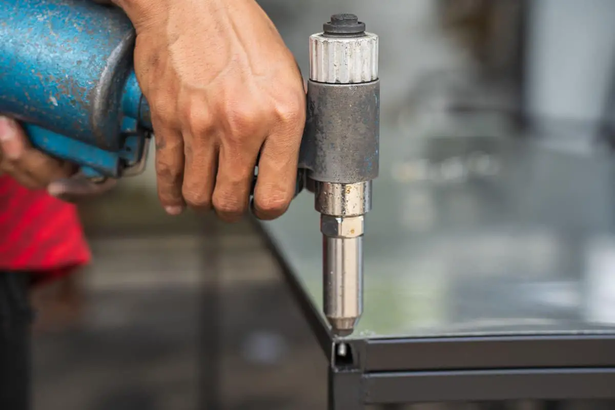
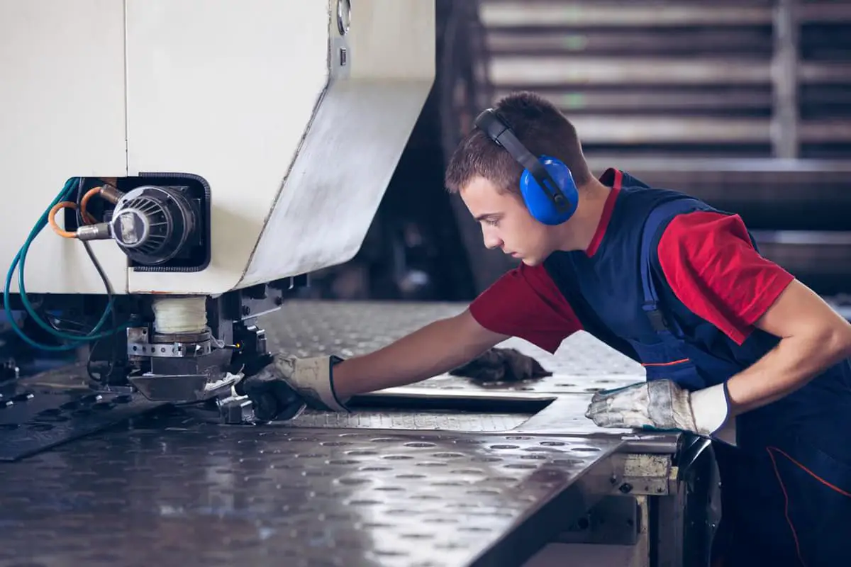
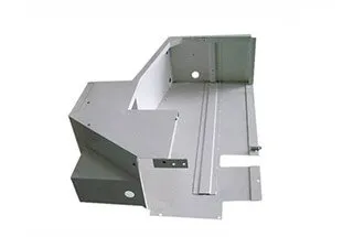
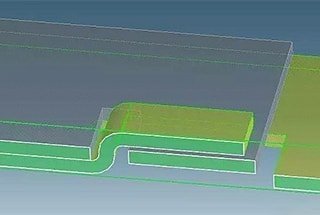
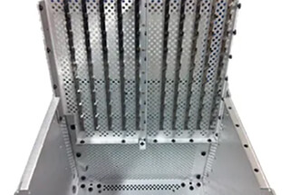
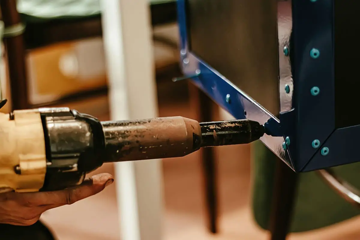
Riveting involves using specialized equipment and tooling dies to apply force and compress or embed the riveted parts into the workpiece, ensuring that it remains secure and vertical. This process is illustrated in Figure 1.
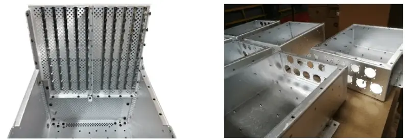
Fig. 1 Riveted parts of communication equipment
Common riveting techniques include radial riveting and rotary riveting. In this section, we will discuss some important precautions and key points for the production control of radial riveting, which is commonly used in our factory (see Fig. 2).
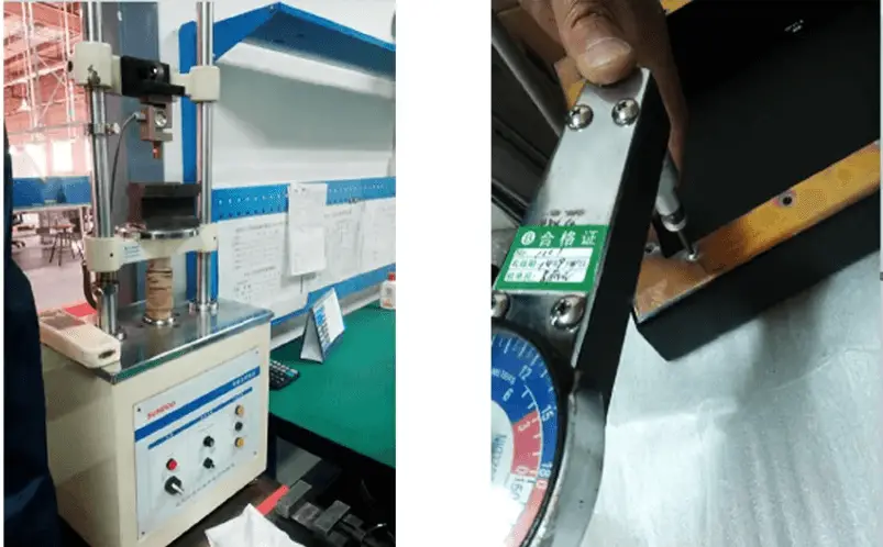
Fig. 2 Radial riveting equipment and riveting process
(1) The size of the riveting bottom hole should be designed in strict accordance with the manuals of general or special equipment, standard parts, and should comprehensively consider the material, thickness, model, and strength requirements of the base material and riveting parts.
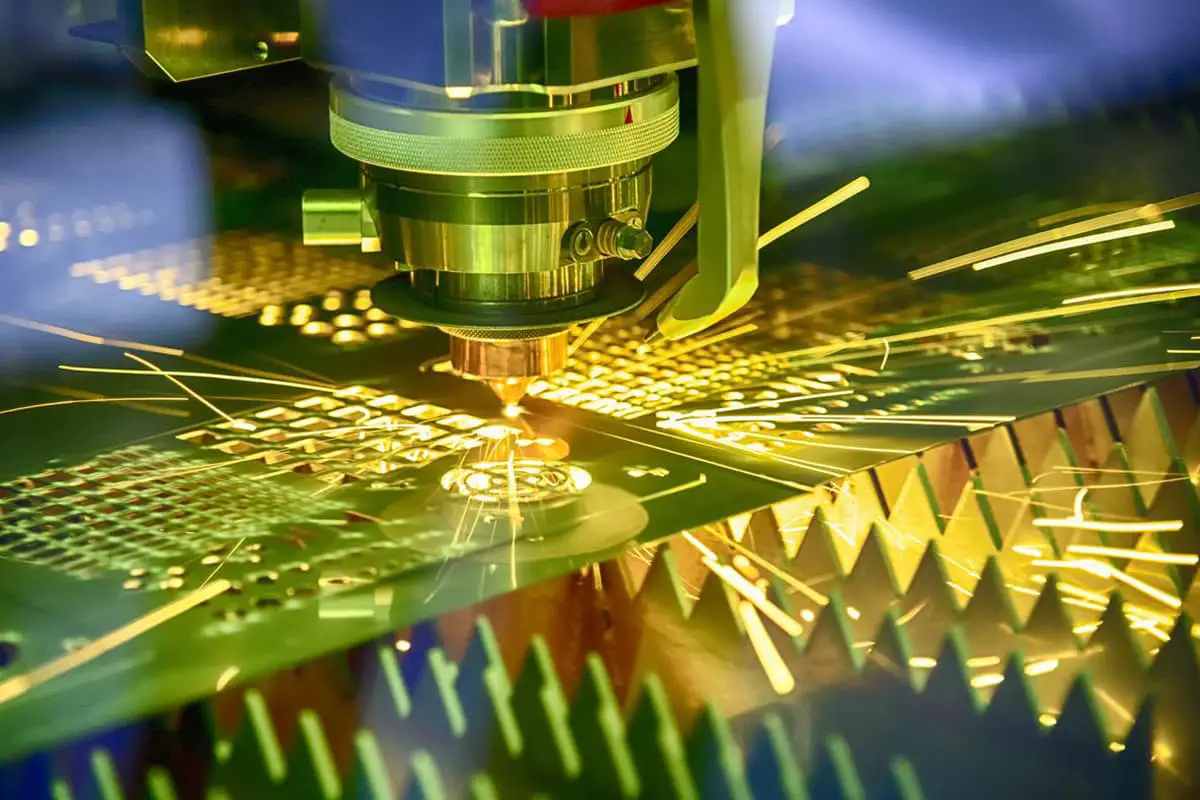
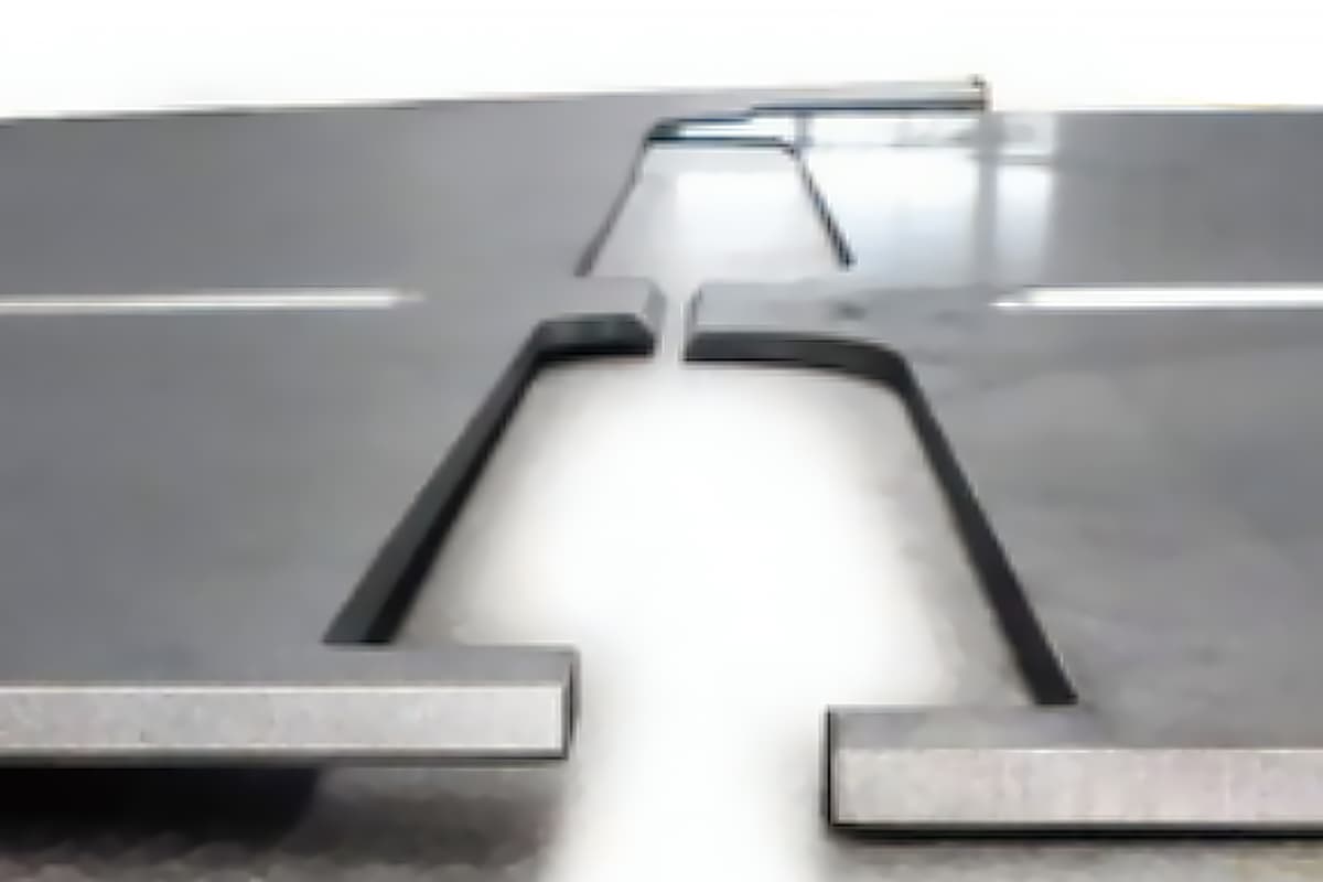
When machining the bottom hole, blanking or laser cutting is commonly used as a pre-processing method. Table 1 compares the two processes of die blanking and laser cutting.
Table 1 Two processes of die blanking and laser cutting
| Pre-process | Die blanking | Laser cutting |
| Bottom hole size | Good accuracy and consistency | The stability of the hole shape and size is slightly poor |
| Substrate change | The blanking tear band is not smooth | There are hardness changes on and around the hole wall |
| Other attention | The burr surface is convex and the smooth surface collapses | Lead, splash and other foreign matters |
For parts with high-quality requirements and large production batches, it is recommended to customize the die, consider the riveting direction, and prioritize the stamping process to create the riveting bottom hole.
If the previous process involves bending, it is necessary to consider whether the riveting bottom hole is located on the bending line (upper).
In this situation, a pre-processing step involves creating a small hole, followed by bending and stretching, and then creating the small hole to the designed size through drilling or reaming.
(2) When selecting the riveting process, it is essential to consider the throat depth of the actual equipment, the form of upper and lower supports, and other conditions to confirm whether it can be carried out successfully.
Furthermore, it is generally recommended to arrange the riveting process after the surface treatment process (such as electroplating, chemical oxidation, spraying, etc.).
If riveting is carried out before surface treatment, it can often lead to issues listed in Table 2.
Table 2 possible problems caused by different surface treatments
| Process | May cause problems |
| Carbon steel electroplating | The zinc layer of stainless steel rivets is peeling, the thread is not smooth, the electroplating solution is stored, and the corrosion is slow under working conditions |
| Aluminum chemical oxidation | The hole diameter of the bottom hole becomes larger, the rivets become loose and the strength decreases |
| Surface spraying | Increase the amount of escaping coating, and it is easy to lead to poor threaded rivets |
(3) For certain specialized products, such as base materials with a thickness ≤ 1.5mm or products with high pressure riveting strength requirements, welding reinforcement may be necessary after pressure riveting.
In cases where welding reinforcement is required, it is recommended not to select galvanized parts for pressure riveting, as this can have an adverse impact on the welding reinforcement process.
The general requirements for the operation of the riveting process are:
Additionally, in the actual production of our factory, we would like to share the following three operational guidelines.
(1) Operators typically judge the firmness of a rivet by observing whether there is a gap between the riveted parts and the substrate or whether there are steps at the riveting position after countersunk riveting. This 100% self-inspection operation is necessary. Additionally, the hardness of the material surface, from galvanized plates to stainless steel and low-carbon steel plates, decreases in turn. Thus, in actual processing, pressure parameters should be adjusted in advance according to the riveting materials. For riveting parts with a risk of falling off, technical requirements for welding and spot reinforcement should be communicated with the customer beforehand.
(2) Riveting operations must be completed in one go to eliminate the need for two rounds of riveting and to reduce the repair of fallen riveted parts, especially for parts with high material surface hardness. The flower teeth and base materials of riveted parts are damaged after repair. If original parts must be repaired, welding reinforcement must be carried out after riveting.
(3) For technical inspection after riveting, inspectors must have the basic ability to spot-check the breaking torque and, if possible, the breaking push-off force. The first article inspection and technical sampling inspection of the riveting process cannot be replaced by an operator’s self-inspection, so this work must be implemented.
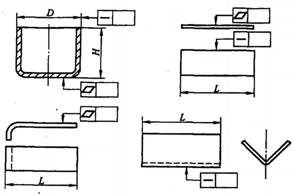
(1) It is important to pay attention to whether the riveting position interferes with adjacent bending edges (lines), outer edges, or weld beads, as this can affect both the quality of the riveting and the appearance of the assembly. Please refer to Table 3 for common riveting interference problems.
Table 3 Common interference problems of riveting
| Type | Example | Proposal |
| Distance from the free edge |
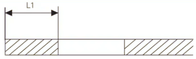 | L1 value reference manual |
| Distance from bend edge |
 | L1 ≥ bending radius and L1 ≥ riveting head radius of riveter |
| Close to the weld bead | Be sure to check for any interference between the riveting parts and the upper and lower dies. If there is interference, the dies may need to be repaired to prevent any air gaps. |
(2) When there are multiple types of riveting standard parts and similar parts on the same component, it is recommended to avoid operating them all on the same machine to prevent mixing and misuse of the riveting parts. Additionally, when there are many riveting parts of the same specification on a component, the riveting sequence should be standardized to prevent missed rivets.
(3) During the riveting process, if the operator needs to leave their post for any reason, such as for eating or shift handover, the worktable must be cleared to ensure that processed and unprocessed parts are not mixed.
(4) If there is a hole near the riveting position, it is important to confirm whether the hole is extruded or deformed after riveting. For pressure-riveted screws and nuts, a thread gauge should be used to detect the through end and stop end after pressure riveting.
Riveting refers to the process of using rivets to connect two or more workpieces, typically sheet metal pieces or components. Riveting can be classified into rivet riveting, pull riveting, and core striking riveting.
In riveting, the component that deforms itself or uses a press-fit connection with the riveted parts is called a rivet. There are many types of rivets, including semi-round head rivets, flat head rivets, semi-hollow rivets, solid rivets, and countersunk rivets.
Cold riveting is generally used for rivets <8mm, and hot riveting is used for rivets ≥8mm. Parameters of rivets and riveting requirements are detailed in most mechanical design handbooks, so they won’t be discussed here.
The rivet riveting process includes: drilling – (grooving) – deburring – inserting rivets – die holding the rivet – rotating rivet machine forming (or manual tightening).
Pull riveting refers to the process of using a pull rivet to connect two components with through holes by pulling the pull rod until it breaks with a pull rivet gun, causing the pull rivet sleeve to expand and become a non-detachable connection.
1) Pull rivets, also known as core-pulling rivets, are a type of rivet used for single-sided riveting. Pull rivets require special tools, such as a pull rivet gun (manual, electric, or pneumatic) for riveting. This type of rivet is especially suitable for situations where ordinary rivets (which require riveting from both sides) are inconvenient.
Therefore, they are widely used in products such as ships, airplanes, machines, and electrical appliances. The most widely used are the open-type shoulder round head pull rivets, countersunk pull rivets suitable for surfaces requiring smooth riveting, and sealed pull rivets suitable for high-load and certain sealing performance riveting situations. When using pull rivets, note that:
A) In the riveting of flat head pull rivets, the side in contact with the rivet head must be countersunk.
B) In the riveting of round head pull rivets, the side in contact with the rivet head should be flat.
2) For pull riveting parameters, see Table 9-17.
Table 9-17 Pull Riveting Parameters
| Rivet Type | Nominal Rivet Diameter (mm) | Steel Plate Rivet Hole Diameter (mm) | Length (mm) | Riveted Steel Plate Thickness /mm | |
| Umbrella-shaped | Flathead | ||||
| Aluminum Rivet | 2.4 | 2.5 | 5.7 | 1.0-3.2 | 1.6~3.2 |
| 7.3 | 3.2-4.8 | 3.2-4.8 | |||
| 8.9 | 4.8-6.4 | 4.8~6.4 | |||
| 3.0 | 3.1 | 6.3 | 1.0~3.2 | 1.6~3.2 | |
| 8.0 | 3.2~4.8 | 3.2-4.8 | |||
| 9.8 | 4.8~6.4 | 4.8~6.4 | |||
| 3.2 | 3.3 | 6.3 | 1.6-3.2 | 1.6-3.2 | |
| 8.0 | 3.2-4.8 | 3.2-4.8 | |||
| 9.8 | 4.8~6.4 | 4.8-6.4 | |||
| 4.0 | 4.1 | 6.9 | 1.6~3.2 | 1.6-3.2 | |
| 8.6 | 3.2-4.8 | 3.2-4.8 | |||
| 10.4 | 4.8-6.4 | 4.8-6.4 | |||
| 4.8 | 4.9 | 7.5 | 1.6-3.2 | 2.3~3.2 | |
| 9.3 | 3.2-4.8 | 3.2-4.8 | |||
| 11.1 | 4.8~6.4 | 4.8~6.4 | |||
| Steel Rivet | 3.2 | 3.3 | 6.4 | 1.0~3.2 | |
| 9.5 | 3.2~6.4 | ||||
| 4.0 | 4.1 | 10.2 | 3.2~6.4 | ||
| 4.8 | 4.9 | 10.8 | 3.2-6.4 | ||
Note:
1. Generally, the through-hole of a part is 0.1~0.2mm larger than the nominal diameter of the blind rivet.
2. Blind rivets can be blackened or otherwise treated to meet product requirements, allowing them to match the color of the workpiece.
3. The center distance of the blind rivet hole from the edge of the base plate should be more than twice the diameter of the blind rivet hole. At this distance, the riveting strength is optimal. If the distance is less, the strength greatly decreases.
Strike-core rivets are another type of single-sided rivet. During riveting, the rivet head is struck with a hammer to release the core, making it flush with the end face of the rivet head, thus completing the riveting.
Its operation is very convenient, especially suitable for riveting situations where it is inconvenient to use ordinary rivets (which require riveting on both sides) or blind rivets (when there is a lack of a rivet gun).
Flat round head strike-core rivets are commonly used, while countersunk strike-core rivets are suitable for situations where a smooth surface is required.
Drawn arc stud welding is one of the methods for directly connecting two sheet metal parts, mainly used for the connection of coated steel plates or stainless steel plates.
One of the sheet metal parts is processed at the connection point to create a countersink hole, while the other has the hole at the connection point flanged. They are riveted together using a riveting mold to form an inseparable connection.
The method of drawn arc stud welding is shown in Figure 9-7.

(1) Advantages of Pull-hole Riveting
The flange and countersink hole combination inherently possess a positioning function. The riveting strength is also high due to the usage of a riveting die, resulting in a higher production efficiency.
(2) Disadvantages of Pull-hole Riveting
It’s a one-time connection and can’t be disassembled.
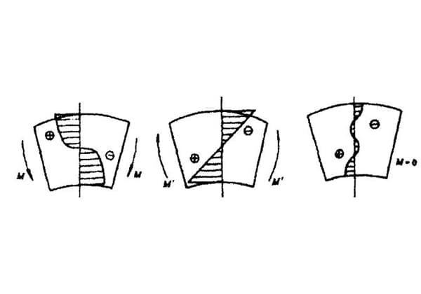
1) Principle of shell matching:
H=t+t’+(0.3~0.4)
When the thickness ‘t’ is greater than or equal to 0.8mm, the flanging hole wall thickness is set at 0.4t.
When ‘t’ is less than 0.8mm, the flanging hole wall thickness is typically set at 0.3mm.
The height ‘h’ is generally chosen to be 0.46±0.12mm.
For the parameters of the drawn hole riveting, refer to Table 9-18.
Table 9-18 presents the drawn hole riveting parameters (in mm).
| Parameter Number | Material Thickness t /mm | Bending Height H /mm | Flange Outer Diameter D/mm | |||||||||||
| 3.0 | 3.8 | 4.0 | 4.8 | 5.0 | 6.0 | |||||||||
| Corresponding to the inner diameter ‘d’ of the straight hole and the bottom hole ‘do‘ of the pre-flanged edge. | ||||||||||||||
| d | d0 | d | d0 | d | d0 | d | d0 | d | d0 | d | d0 | |||
| 1 | 0.5 | 1.2 | 2.4 | 1.5 | 3.2 | 2.4 | 3.4 | 2.6 | 4.2 | 3.4 | ||||
| 2 | 0.8 | 2.0 | 2.3 | 0.7 | 3.1 | 1.8 | 3.3 | 2.1 | 4.1 | 2.9 | 4.3 | 3.2 | ||
| 3 | 1.0 | 2.4 | 3.2 | 1.8 | 4.0 | 2.7 | 4.2 | 2.9 | 5.2 | 4.0 | ||||
| 4 | 1.2 | 2.7 | 3.0 | 1.2 | 3.8 | 2.3 | 4.0 | 2.5 | 5.0 | 3.6 | ||||
| 5 | 1.5 | 3.2 | 2.8 | 1.0 | 3.6 | 1.7 | 3.8 | 2.0 | 4.8 | 3.2 | ||||
The above content summarizes the experience gained from handling common issues and operations during the riveting process in sheet metal production and processing.
It is worth noting that some factories have partially achieved the automation of automatic feeding mechanisms and riveting. This automation solution is beneficial in avoiding human errors to a great extent. However, the degree of automation implemented varies due to factors such as cost, technology, product variety, type, and batch size.
Whether you opt for manual operation, semi-automatic or fully automatic production scheme, the information presented above can be useful in your production process.

As the founder of MachineMFG, I have dedicated over a decade of my career to the metalworking industry. My extensive experience has allowed me to become an expert in the fields of sheet metal fabrication, machining, mechanical engineering, and machine tools for metals. I am constantly thinking, reading, and writing about these subjects, constantly striving to stay at the forefront of my field. Let my knowledge and expertise be an asset to your business.