Bend Allowance Formula: Calculator & Charts
Have you ever wondered how to precisely calculate the bending allowance for your metal fabrication projects? In this blog post, we'll explore the fascinating world of bend allowance formulas and…
Ever wondered how press brake crowning devices affect bending precision? This article explores two main compensation methods: lower die convex compensation and upper die convex compensation. It examines their impact on reducing angle errors and enhancing straightness during bending. By understanding these techniques, readers can learn how to achieve higher accuracy in their press brake operations.
When a press brake bends a workpiece, the ram and the worktable deform under the force of the bending. At this point, the depth of the upper die entering the lower die opening does not align with the entire length of the workpiece, causing a significant decrease in the precision of the workpiece.
To address this issue, various deformation compensation devices have been developed and can be broadly classified into two categories.
The first category involves the worktable being designed with a convex shape that rises in the middle, forming a symmetrical curve. This is referred to as “lower die convex compensation.
The second category involves the upper die or ram being raised with a symmetrical curve that dips in the middle. This is called “upper die convex compensation.”
For simplicity of description and expression, the ram and the worktable are represented as slender rectangles.
Without any compensation, the ram and worktable deform under the force of bending. At this time, the compensation convexity value (f) is equal to zero, with the ram deformation being (f1) and the worktable deformation being (f2).
To correct this, the compensation device is activated, setting the compensation convexity value (f) equal to (f1 + f2).
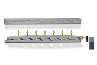
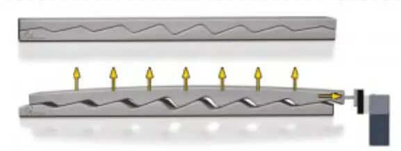
In an ideal scenario, the depth of the upper die entering the lower die opening remains consistent throughout the entire die length, resulting in a uniform bending angle of the sheet metal. Although achieving this ideal scenario is challenging, people continually strive to get as close as possible.
From the analysis above, it can be concluded that both compensation devices can effectively reduce the angle error of the bent parts. However, their impact on straightness is different.
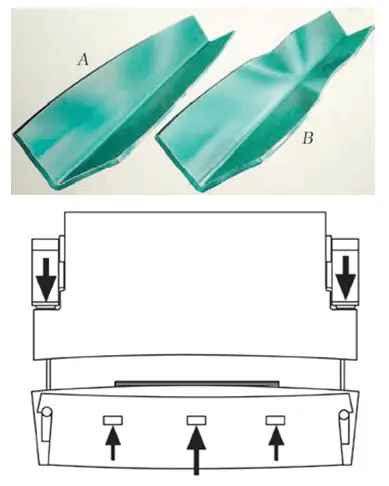
After bending, the edge of the bent part will naturally flex, with its maximum deflection being described by δ.
During the bending process, the metal in the deformation area undergoes high levels of plastic deformation. In this zone, the inner layer of the circular arc experiences longitudinal compressive stress parallel to the OX direction, while the outer layer experiences longitudinal tensile stress.
These opposing tensile and compressive stresses create a longitudinal moment (My) rotating around the OY axis, which is necessary to maintain the longitudinal direction (OX direction) of the bent part in alignment with the corresponding longitudinal line of the die during bending.
Once the ram returns and the bending force and longitudinal moment are removed, the metal layers in the deformation area quickly rebound. As a result, natural bending occurs in the opposite direction of the longitudinal moment in the longitudinal direction.
For ease of expression, the bending deformation zone is considered as a plane. Under the influence of the bending force, the upper layer (circular inner) of metal experiences longitudinal compression and the lower layer (circular outer) experiences longitudinal tension.
When a lower die is fitted with convex compensation, the compensating convexity curve rises upward. Conversely, when an upper die is fitted with convex compensation, the compensating convexity curve dips downward.
The natural deflection curve of the bent part is an upward bulge. The value of the compensating convexity is determined by the deformation of the ram and worktable during bending and is relatively small.
Due to the compensation convexity, the deflection caused by springback will be reduced. As a result, the deflection caused by the compensating convexity is typically lower than the natural deflection (δ) of the bent part.
Once the hydraulic cylinder is filled with pressurized oil, the crossbeam will rise upward and form a set of controllable convex curves. This design is widely used in CNC press brakes and has the following characteristics:
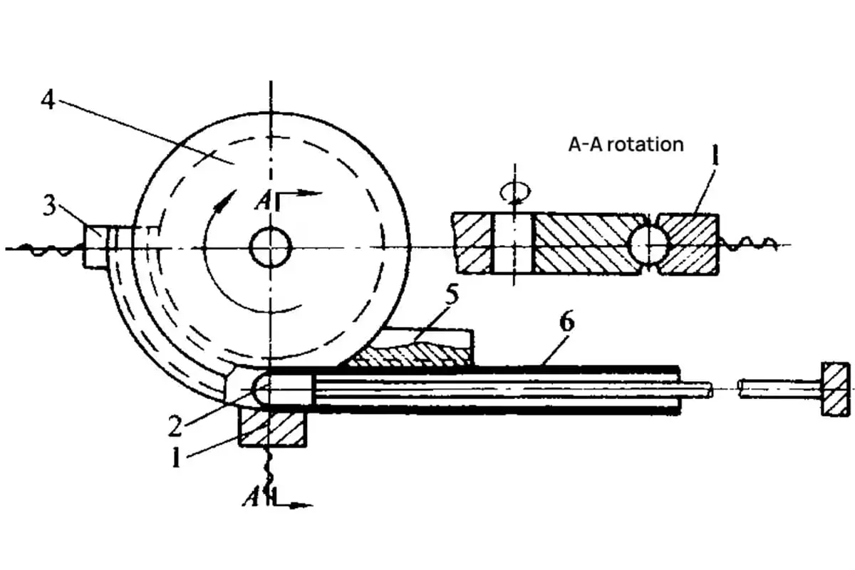
The worktable is equipped with multiple groups of wedges located underneath it. The angle of each group is designed to meet specific requirements. The horizontal position of the upper wedge in each group of wedges is fixed, while the lower wedge moves to the left simultaneously.
As the working table rises upward to meet design requirements, this design has become widely used in various types of press brakes.
The following are the characteristics of this design:
Multiple modules are positioned between the ram and the upper die, with each group of wedges having the same specifications. The connecting plate and lower wedge of the wedge are fixed as a unit. By moving the upper wedge, a downward convex curve can be achieved. Finally, the modules are secured between the ram and the upper die by a pressing plate.
The following are the characteristics of this design:
A group of hydraulic cylinders is installed in the center of the ram. Once the cylinders are filled with pressurized oil, the middle part of the ram will descend, creating a controllable local convex curve.
However, due to structural limitations, the two sides of the ram cannot be effectively compensated, making this method of compensation less widely used.
The following are its characteristics:
During press brake operation, the compensating convexity should match the deformation of the ram and worktable. This requires the ability to adjust the compensating convexity quickly and easily along the entire die length.
However, the current design of punch convex compensation makes it difficult to meet this requirement, limiting its use.
To enhance the accuracy of press brake operation and fully utilize the benefits of upper die convex compensation, developing a new structure for rapid control of the upper die crown is a promising direction for the future development of press brakes.
Currently, some organizations have made positive attempts in this field and achieved promising results.

As the founder of MachineMFG, I have dedicated over a decade of my career to the metalworking industry. My extensive experience has allowed me to become an expert in the fields of sheet metal fabrication, machining, mechanical engineering, and machine tools for metals. I am constantly thinking, reading, and writing about these subjects, constantly striving to stay at the forefront of my field. Let my knowledge and expertise be an asset to your business.