I. The Difference Between Brass and Copper
Brass
Brass is a yellow-colored alloy composed of copper and zinc. Ordinary brass is made up of only these two elements, while special brass is composed of more than two elements, such as lead, tin, manganese, nickel, iron, and silicon.
Brass with a copper content of 62% to 68% has a melting point ranging from 934 to 967 degrees. It is known for its strong wear resistance and good mechanical properties, making it suitable for use in the manufacturing of pressure equipment.
Special brass is also known for its high strength, hardness, and resistance to chemical corrosion. This makes it a popular choice for the production of seamless pipes, which can be used in applications such as heat exchangers, condensers, low-temperature pipelines, and submarine transportation pipes.
In addition to pipes, brass can also be used to manufacture sheet metal, bars, castings, and other products. With its strong plasticity and high copper content, brass is an ideal material for the manufacturing of pressure equipment.
Red copper
Red copper is a type of copper that gets its name from its reddish-purple color. It is also known as industrial pure copper and is composed solely of copper.
Red copper has a melting point of 1083°C and does not undergo isomeric transformation. Its relative density is 8.9, which is five times greater than that of magnesium. It is also about 15% heavier than ordinary steel.
When an oxide film forms on its surface, red copper takes on a reddish-purple hue, which is why it is referred to as red copper. This copper also contains a certain amount of oxygen and is sometimes referred to as oxygen-containing copper.
II. Brass Welding Method
The methods for welding brass include gas welding, carbon arc welding, manual arc welding, and argon arc welding.
1. Gas welding of brass
Gas welding is the most widely used method in brass welding due to the low temperature of the gas welding flame, which reduces the evaporation of zinc in brass compared to electric welding methods.
The welding wires commonly used for brass gas welding are wire 221, wire 222, and wire 224. These wires contain elements such as silicon, tin, and iron, which help prevent and reduce the evaporation and burning loss of zinc during the welding process, ensuring the quality of the weld and preventing the formation of pores.
Two types of flux are commonly used in gas welding brass: solid powder and gas flux. The gas flux is made up of methyl borate and methanol, such as gas agent 301. This flux helps to improve the quality of the weld and prevent contamination.
2. Manual arc welding of brass
In addition to copper 227 and copper 237, self-made electrodes can also be used for brass welding. During brass arc welding, it is recommended to use a DC power supply with the positive electrode connected to the workpiece and the negative electrode connected to the electrode.
Before welding, it is important to thoroughly clean the surface of the workpiece. The groove angle should be between 60 to 70 degrees to ensure proper weld formation.
To improve the quality of the weld, the workpiece should be preheated to a temperature between 150 to 250°C. During welding, it is recommended to use a short arc and a linear movement without any transverse or back and forth swings. The welding speed should be high for best results.
It is important to note that brass weldments that come into contact with corrosive media, such as seawater and ammonia, should be annealed after welding to relieve any welding stress.
3. Manual argon arc welding of brass
Standard brass welding wires such as wire 221, wire 222, and wire 224 can be used for brass manual argon arc welding. Alternatively, filling materials with the same composition as the base metal can be used.
Both DC positive connection and AC welding can be used for this process. When using AC welding, the evaporation of zinc is less compared to when using DC positive connection.
In most cases, preheating is not necessary before welding. However, if there is a significant difference in plate thickness, preheating may be required.
It is recommended to weld as fast as possible to achieve optimal results. After welding, the weldment should be heated to a temperature between 300 to 400°C for annealing to relieve any welding stress and prevent cracks during use.
4. Brass carbon arc welding
For brass carbon arc welding, wire 221, wire 222, and wire 224 can be selected based on the composition of the base metal. Alternatively, self-made brass welding wire can also be used.
Gas flux 301 can be used as a flux during welding.
It is recommended to use short arc welding to minimize the evaporation and burning loss of zinc.
III. Red Copper Welding Method
Red copper, also known as industrial pure copper, can be welded using various methods such as gas welding, manual carbon arc welding, manual electric arc welding, manual argon arc welding, and automatic welding for larger structures.
1. Gas welding of red copper
Butt joints are the preferred method for welding red copper, with lap joints and T-joints being used only as needed. There are two options for welding wires in gas welding: welding wires that contain deoxidizing elements, such as wires 201 and 202, or a combination of general copper wire and base metal, using gas agent 301 as flux. A neutral flame should be used during the gas welding of red copper.
2. Manual arc welding of red copper
In manual arc welding, red copper welding rod copper 107 is used with a red copper (T2, T3) welding core. Before welding, it is important to clean the edges of the welding joint.
If the thickness of the workpiece is greater than 4mm, preheating is necessary, with a temperature of approximately 400 to 500°C. The copper 107 electrode should be used for welding and a DC reverse connection power supply should be adopted.
During welding, a short arc should be used and the welding rod should not move laterally. A reciprocating linear motion of the welding rod can improve the formation of the weld. For long welds, the step-by-step back welding method should be used. The welding speed should be as fast as possible.
When welding multiple layers, it is important to remove any slag between the layers. Welding should be carried out in a well-ventilated area to prevent copper poisoning. After welding, the weld should be flattened using a hammer to relieve stress and improve the quality of the weld.
Related reading: How to Choose the Right Welding Rod?
3. Manual argon arc welding of red copper
In manual argon arc welding of red copper, welding wires such as wire 201 (special red copper welding wire), wire 202, and T2 red copper wire can be used. Before welding, it is important to clean the welding edges of the workpiece and the surface of the welding wire of any oxide film, oil, or other contaminants to prevent defects such as pores and slag inclusions. This can be done through mechanical or chemical cleaning methods.
The size of the groove made in the workpiece depends on its thickness. If the thickness is less than 3mm, no groove is needed. For 3 to 10mm thickness, a V-groove should be opened with a 60 to 70 degree angle. If the thickness is greater than 10mm, an X-groove with a 60 to 70 degree angle should be made. It is generally recommended to avoid blunt edges to prevent incomplete penetration. The clearance for butt joints should be between 0.5 to 1.5mm, depending on the plate thickness and groove size.
DC positive connection is usually used for manual argon arc welding of red copper, with the tungsten electrode connected to the positive electrode. To prevent pores and ensure reliable fusion and penetration of the weld root, it is necessary to increase welding speed, reduce argon consumption, and preheat the workpiece. The preheating temperature should be between 150 to 300°C for workpieces less than 3mm thick, and between 350 to 500°C for workpieces thicker than 3mm. The preheating temperature should not be too high, as this may reduce the mechanical properties of the welded joint.
4. Carbon arc welding of red copper
Carbon arc welding can also be used for red copper. Carbon electrodes and graphite electrodes can be used as the welding electrodes, and the welding wire used is the same as that used in gas welding. The base metal can also be cut, and gas flux 301 can be used as the flux.
IV. Examples of Copper Alloy Welding
Example 1. Manual Tungsten Inert Gas (TIG) Welding of Copper Tubing
During equipment installation, a company needed to weld six copper tubes (model T2) with dimensions of Φ180mm×10mm. For this task, manual tungsten inert gas welding was employed with great success. The welding process steps were as follows:
1. Pre-Welding Preparation
1.1 The welding equipment used was a WSE-350 AC/DC TIG welding machine with DC positive polarity. The chosen welding material was copper welding wire (wire 201), with a diameter of 3mm. The purity of the argon gas was ≥99.96%.
1.2 The bevels were aligned with no gaps left between them.
1.3 The welding area of the copper tube and the copper wire were kept free from oil, oxidation layers, moisture, and other contaminants, and exhibited a metallic luster.
1.4 Welding parameters: A Φ3mm cerium tungsten electrode was used along with a Φ14mm nozzle. The welding current was set between 160~180A, and the argon gas flow was 15L/min.
1.5 Preheating: Due to copper’s high thermal conductivity and coefficient of thermal expansion, as well as its brittleness when heated, the bevel of the copper tube and the 60mm area on either side were preheated prior to welding. This preheating was performed using an oxy-acetylene flame, reaching a temperature of approximately 500℃. The temperature was measured with a point contact thermometer.
1.6 Two areas of the tube were tack welded (dividing the circumference of the tube into three equal parts, two of which were tack welded and one was the starting point of the weld). The tack welds had a required length ≥10mm and a suitable weld height of 3mm.
2. Welding Procedure
The welding process was done in two layers: a root run and a cap run. All welding was done in the rotational welding position, specifically between 10 and 11:30 on a clock face, with a random upward rotation during welding.
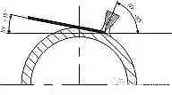
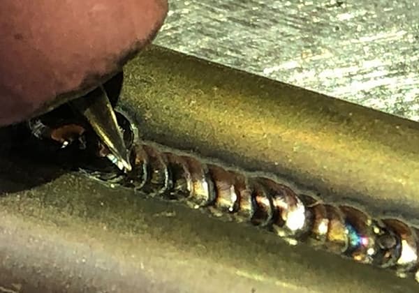
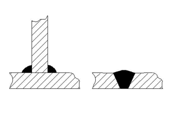
2.1 Root Run: The root run was carried out using a leftward welding technique. During welding, steps were taken to prevent the formation of gas pockets, slag inclusions, weld spatter, and incomplete penetration. The angle between the welding wire and the tube surface was kept as small as possible to improve the effectiveness of the argon shielding, as shown in Figure 7.
Ensure smooth movement of the welding gun and appropriate control of the weld pool temperature. It should be neither too high nor too low for the welding process to proceed smoothly. It is crucial to closely monitor the flow of the molten copper in the weld pool and master the timing of melting and penetration.
When the molten metal in the weld pool starts to sink slightly, it indicates penetration (with basic good root formation).
Adopt an “interrupted” wire feeding method for filler wire insertion, that is, the copper welding wire advances and retreats alternately. The wire should feed “swiftly” and retreat “cleanly”, maintaining this state while welding uniformly forward. If the welding speed is slightly slow or penetration is uneven, incomplete penetration or burn-through may occur, resulting in welding nodules. The arc striking, joint, and operation method are the same as the previously mentioned argon arc welding method.
2.2 Welding of the cover layer: The welding gun swings left and right, and the welding wire feeds with the movement of the welding gun. When the arc moves to both sides of the groove, pause slightly and add welding wire to fill the groove and rise 1.5~2mm above the tube surface. The welding gun and welding wire should cooperate appropriately and swing evenly to control the consistency of the weld pool shape and produce a weld of excellent quality inside and out.
3. Precautions:
1) During welding, “tungsten touching” (i.e., the tungsten electrode contacts the welding wire or the weld pool) is strictly forbidden. If “tungsten touching” occurs during welding, a large amount of metallic dust and vapors will enter the weld pool, resulting in numerous honeycomb-shaped pores or cracks in the weld. If “tungsten touching” occurs, stop welding, treat it by grinding clean, and replace the tungsten electrode or resharpen the tungsten tip until the metal is free of copper spots.
2) Ensure firm contact of the overlapping lines and avoid scratching the tube surface.
3) After the weld cools slightly, rotate the pipe and pad it firmly.
4) Control the interlayer temperature. If welding fusion becomes difficult, it indicates a low temperature. Reheat to above 500℃ before welding again to prevent incomplete fusion or poor fusion defects.
5) Ensure good fusion, slightly faster welding speed, and suitable wire feeding. Pay attention to the simultaneous melting of the base metal and welding wire to merge into one to prevent incomplete fusion or poor fusion defects.
6) When extinguishing the welding arc, the welding gun should not be lifted immediately. Continue to use the post-flow shielding gas function to protect the weld pool to prevent the formation of pores.
4. Post-welding treatment:
After inspection, if there are no defects such as pores, cracks, or slag inclusions, reheat the welded pipe joint’s welding area to 600~700℃, and then quench it with tap water to increase the plasticity of the welding area.
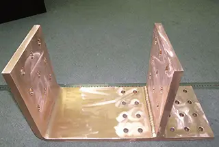
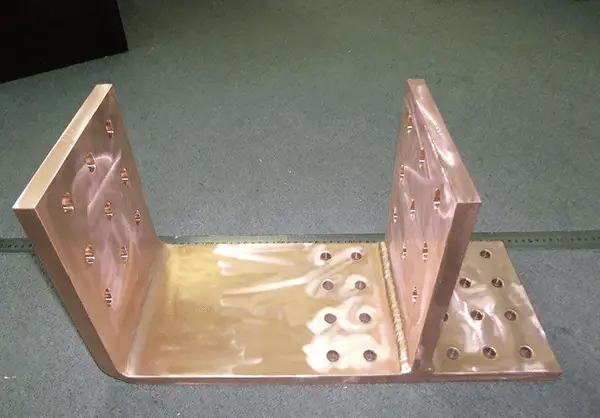
Example 2: Oxy-acetylene welding of a δ=2mm thin sheet of purple copper
The waterstop in the cooling pool of the blast furnace is composed of δ=2mm thin purple copper sheets welded together. Welding is challenging due to the excellent thermal conductivity of copper.
Either the temperature is insufficient to form a melt pool, resulting in unmerged or poorly fused metal in the weld, or the temperature is too high, causing a large area of the welding zone to melt, resulting in welding defects such as burn-through or weld lumps. Welding thin purple copper sheets is a rather “tricky” problem.
The problem can be effectively solved by using “brass brazing” welding method. The preparations before welding and the welding operation process are as follows:
1) Decontaminate 60mm on each side of the weld seam and use a steel wire brush to polish it to reveal the metallic luster.
2) The workpieces are paired without a groove, and the pairing gap should be less than 1mm.
3) Use Ф3mm silicon brass welding wire (wire 224) with welding flux 301.
4) Level the area to be welded (the pad is made of flat steel plate, which should be thicker to prevent thermal deformation).
5) Preheat. Two welders use medium welding torches and neutral flames to heat the welding area simultaneously, reaching a temperature of 500~600℃. One person welds, and the other continues to heat the welding location to ensure the stable progress of the welding process.
6) The preheating welder uses a neutral flame, and the welding welder uses a slight oxidizing flame.
7) Spot welding and formal welding should be carried out continuously, with a spot welding distance of 60~80mm. The spot welding point should be smaller.
8) Pay close attention to the temperature changes in the welding area during heating and welding to prevent it from being too high or too low. Generally, visually judge by dark red (550~600℃).
9) The movement of the welding nozzle should be steady, and move forward at a uniform speed. The flame core (white point) should be 5~8mm above the melt pool. The outline of the flame should always cover the melt pool to avoid contact with air. Ensure the brass liquid naturally and smoothly spreads to both sides of the weld and penetrates into the gap.
10) To make the crystalline structure of the welded joint denser and improve its strength and toughness, tap the weld with a small hammer after welding.
11) Perform a leak-tightness test after welding.