Copper Busbar Welding: Techniques and Best Practices
What makes copper busbar welding so crucial yet challenging? This article delves into the high conductivity, thermal properties, and specific welding techniques required for copper busbars in power construction. From understanding thermal cracking to mastering TIG welding methods, it offers a comprehensive guide on achieving optimal welding results. Learn about the intricacies of welding materials, pre-welding preparations, and key process parameters that ensure high-quality welds, setting a new standard in welding technology.
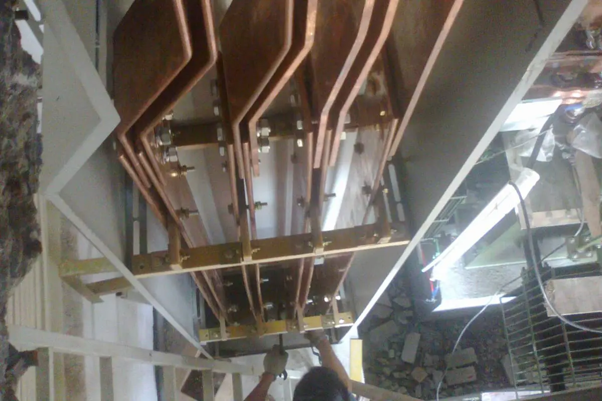
Copper busbar welding is not common in our company’s power construction due to its high requirements and difficulty. However, copper busbars, with their superior conductivity, were chosen for the electrical busbars in the coal-fired power plant.
After conducting welding experiments and product welding applications, the welding subsidiary has essentially mastered the welding technology of copper busbars, laying a foundation for future copper busbar welding in our company and advancing our welding technology to a new level.
1. Copper Busbar Welding Characteristics and Process
The connection of copper busbars in power stations mainly involves two methods: bolt fastening and welding. Copper has excellent electrical conductivity, thermal conductivity, heat resistance, and formability. Industrial pure copper is not less than 99.5% ωcu.
2. Copper Welding Characteristics
2.1 High Thermal Conductivity
The thermal conductivity of pure copper at room temperature is 8 times greater than that of carbon steel. To heat a pure copper workpiece to its melting temperature, a large amount of heat is required.
Therefore, a concentrated heat source is needed during welding; otherwise, heat will dissipate quickly. Preheating should be performed on the workpiece when welding pure copper.
2.2 High Thermal Cracking Sensitivity
Various copper base materials always contain a certain amount of impurities that form a low-melting eutectic. The presence of a low-melting eutectic film in the solidified workpiece or heat-affected zone can cause cracks under welding stress.
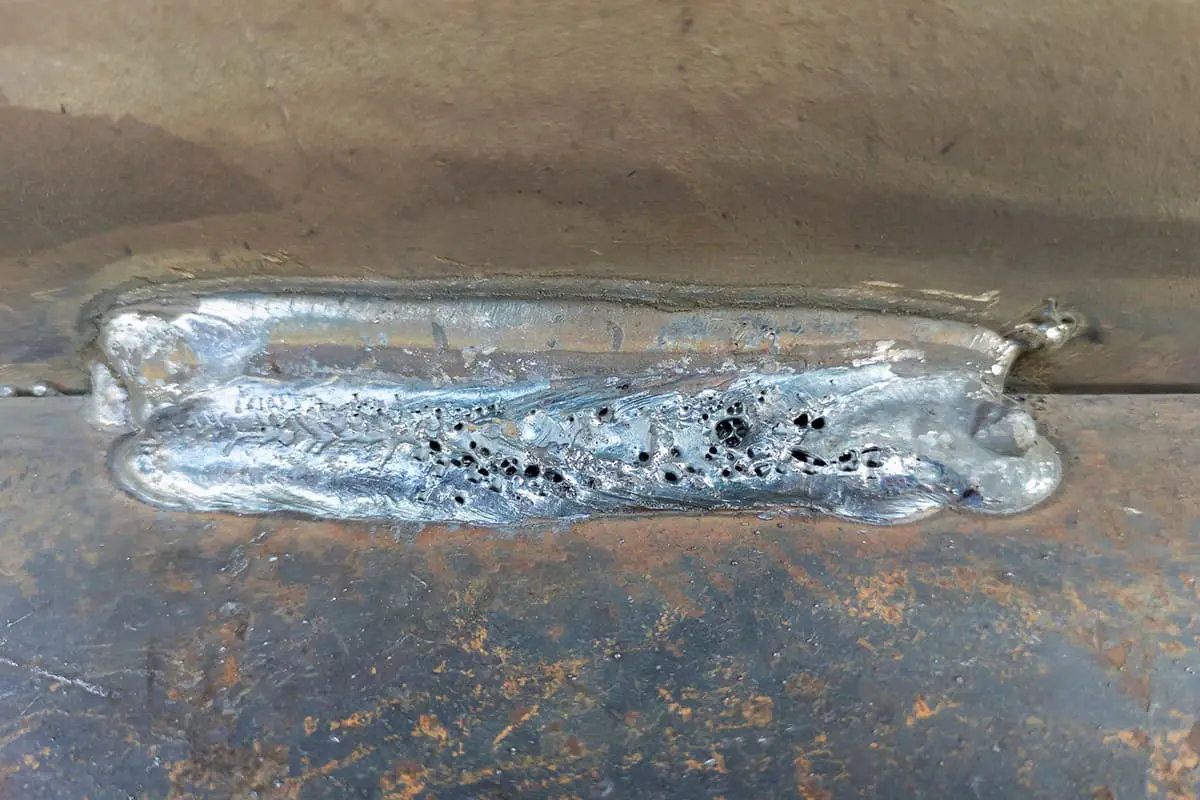
2.3 High Pore Tendency
Pores in the copper weld metal are mainly caused by hydrogen. When pure copper contains a certain amount of oxygen or when CO gas is dissolved in pure copper, pores may also be caused by water vapor and by the reaction of CO with O to generate CO2 gas.
Generally, pores are distributed in the center of the weld and near the fusion line.
2.4 Deterioration Tendency of Joint Performance
During welding, copper inevitably undergoes oxidation and burnout to some extent, resulting in various welding defects. This could potentially lead to a decrease in the strength, plasticity, corrosion resistance, and electrical conductivity of the welded joint.
In the copper fusion welding process, the grain size in the weld and heat-affected zone significantly increases, affecting the mechanical properties of the joint to a certain degree.
To improve the performance of the joint, it’s not only crucial to minimize thermal effects but also to control the impurity content of the weld, and to modify the weld metal through alloying.
3.Welding Process of Copper Busbars
3.1 Selection of Welding Method
The most common welding methods for copper are gas welding and manual tungsten inert gas (TIG) welding.
However, to enhance welding quality, manual TIG welding is preferred. This welding method is superior due to its concentrated heat, easy-to-control weld pool, and particularly its effectiveness when welding materials with a thickness (δ) of less than 12mm.
TIG welding provides stable arc, excellent protection, and flexible operation, making it particularly suitable for medium-thickness welding.
3.2 Selection of Welding Materials
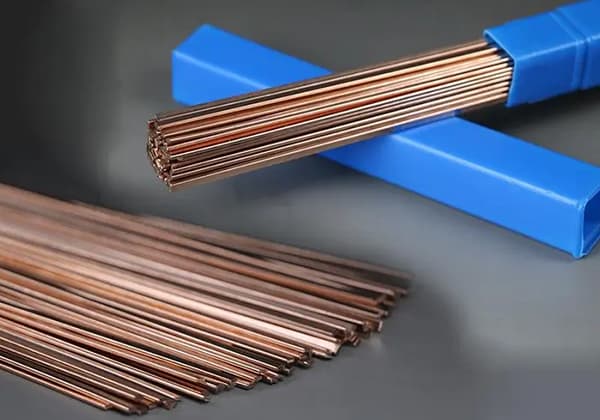
The welding materials for copper refer to welding wires and fluxes. Filling welding wire: When performing manual TIG welding, it’s necessary to manually add filling welding wire. The brand, composition of the welding wire, and the welding processability, joint mechanical properties, and corrosion resistance are all closely related.
When choosing the filling welding wire, the first considerations must be the base metal’s brand, plate thickness, product structure, and construction conditions.
Therefore, when welding copper busbars, a filling welding wire with a composition similar to the base metal is selected. The technical parameters of the copper welding wire are shown in Table 1.
Table 1: Technical Parameters of Copper Welding Wire
Grade
GB Standard Model
Primary chemical composition
Mass Fraction (%)
Melting Point
Primary Use
HS201 (Scu-2)
HSCu
Sn-1.1
Si-0.4
1050
Pure Copper Tungsten Arc Welding (Use of Flux 301)
HS201(Scu-2)
Mn-0.4
Copper (remained)
Technical Parameters of Copper Welding Wire
Solder: During argon arc welding, the surface of molten pool metal tends to oxidize to form cuprous oxide (Cu2O). Its presence often leads to defects such as weld porosity, cracks, and slag inclusions. Technical parameters of the solder are shown in Table 2.
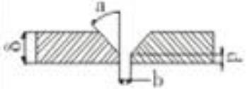
4. Pre-Welding Preparation
Pre-welding preparation primarily refers to the cleaning of the workpiece and welding materials, and the design and processing of the groove before welding.
It’s crucial to clean the surface of the welding wire and both sides of the copper plate groove within 30mm to remove grease, moisture, oxides, and other impurities. Groove processing is performed with an air chisel or a beveling machine.
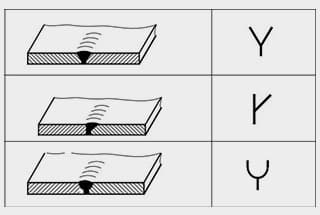
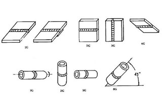
The copper welding groove processing types are presented in Table 3.
5.3 The welding wire for the copper busbar should be HS201 pure copper wire. The flux CJ301 is added and then mixed with anhydrous ethanol (alcohol) to a paste-like consistency, which is then brushed onto the beveled surface of the weldment before welding;
5.4 The welding wire is heated and coated with CJ301 prior to welding;
5.5 For the selection of welding process parameters, manual tungsten arc welding uses direct current electrode positive (DCEP); the pure copper welding process parameters are as shown in Table 4;
5.6 The welding machine should function well, with flexible current adjustment and convenient operation;
5.7 The preheating method for the copper busbar is either electrical or flame heating;
5.8 For preheating temperature selection, parts with a thickness δ less than 4mm can be appropriately preheated, while those with a thickness δ greater than 4mm should be preheated to a temperature of 600-650℃;
5.9 Welding under restraint conditions should be avoided as much as possible. Strict control of interpass temperature during the welding process is necessary, using small swing and low line energy welding;
5.10 The weld seam should be tack welded, with a length not less than 10mm. The number of tack welds should be evenly distributed and no less than three;
5.11 For welding parts with a thickness δ greater than 4mm, a multi-layer multi-pass welding process should be used;
5.12 Black spots caused by high temperatures during welding should be cleaned promptly. Interpass cleaning should be performed using a stainless steel wire brush;
5.13 The quality of the tack welds should be checked prior to welding. Welding can proceed only after it has been confirmed that there are no defects;
5.14 Intermediate inspection steps should be strengthened. For example, after tack welding, between weld layers, and after all welding is completed, inspections should be carried out strictly according to welding process requirements to ensure welding quality.
As the founder of MachineMFG, I have dedicated over a decade of my career to the metalworking industry. My extensive experience has allowed me to become an expert in the fields of sheet metal fabrication, machining, mechanical engineering, and machine tools for metals. I am constantly thinking, reading, and writing about these subjects, constantly striving to stay at the forefront of my field. Let my knowledge and expertise be an asset to your business.
Welding symbols may seem like a foreign language, but mastering them is crucial for effective communication in the world of mechanical engineering. In this blog post, a seasoned mechanical engineer…
Ever wondered how skyscrapers stand tall or cars stay welded together? This blog uncovers the magic behind electric welding machines. Learn about top manufacturers like Lincoln Electric and Miller Welds,…
Have you ever wondered how the sleek cars, sturdy bridges, and advanced airplanes of today are built? This article explores six cutting-edge welding technologies that are revolutionizing manufacturing, from laser…
Have you ever wondered why some welded structures fail unexpectedly? This article explores the hidden forces at play—welding stress and deformation. Learn how these stresses impact strength, stability, and accuracy,…
Have you ever wondered how to calculate the consumption of welding rods accurately? In this blog post, we'll explore the methods and formulas used by industry experts to estimate welding…
Have you ever wondered about the art of welding and the different positions involved? In this fascinating blog post, we'll delve into the intricacies of welding positions, from flat to…
Ever wondered what "X-weld" or "tack-weld" means? Our latest article breaks down 292 crucial welding terms, offering clear definitions and practical examples. Whether you're a seasoned welder or just starting,…
Why does argon arc welding sometimes produce pores, and how can we fix it? Welding porosity, often caused by impurities, improper gas flow, or incorrect technique, can weaken welds and…
Imagine a machine that welds with precision, never tires, and enhances safety in industrial settings. This article explores the fascinating world of arc welding robots, detailing their components, operational procedures,…