Welding of Quenched and Tempered Steels: Explained
Imagine trying to weld a material so strong that it resists wear and tear, yet so tricky that improper technique could lead to catastrophic failure. This is the challenge faced when welding quenched and tempered steels. In this article, you’ll discover the key characteristics of these materials, the specific welding methods and materials required, and crucial tips for pre- and post-welding treatments. By understanding these principles, you’ll learn how to achieve welds that maintain the steel’s remarkable strength and durability. Dive in to master the complexities of welding quenched and tempered steels.
1. Welding of Low Carbon Low Alloy Quenched and Tempered Steels
1. Welding Characteristics of Low Carbon Low Alloy Quenched and Tempered Steels
Low carbon low alloy quenched and tempered steels generally have high yield strength (450-980MPa), good ductility, toughness, and resistance to wear and corrosion. Depending on the intended application, different alloy compositions and heat treatment processes can be employed to obtain low carbon low alloy quenched and tempered steels with different comprehensive properties.
Low carbon quenched and tempered steels typically have a wC (carbon equivalent) content of not exceeding 0.21%, which gives them better weldability compared to medium carbon quenched and tempered steels.
However, in order to successfully weld this type of steel, it is necessary to understand the welding characteristics of these steels, develop the correct welding procedure, and strictly implement it.
The main welding characteristics of low carbon quenched and tempered steels are the tendency to form cold cracks and reduced toughness in the coarse grain zone of the heat-affected zone. To reliably prevent the formation of cold cracks, strict control of hydrogen sources during welding and the selection of appropriate welding methods and parameters are necessary.
Generally, low carbon quenched and tempered steels have low C and S content and higher Mn content or Mn/S ratio, resulting in a lower susceptibility to hot cracking. However, if the steel has higher C and S content or a lower Mn/S ratio, the susceptibility to hot cracking increases. By using low heat input welding parameters and controlling the shape of the weld pool, the generation of such cracks can be prevented.
2. Selection of Welding Methods for Low Carbon Low Alloy Quenched and Tempered Steels
The most commonly used welding methods for low carbon quenched and tempered steels are shielded metal arc welding (SMAW), gas metal arc welding (GMAW), submerged arc welding (SAW), and tungsten inert gas welding (TIG).
By using these arc welding methods with general welding parameters, the cooling rate of the welded joint is relatively high, resulting in mechanical properties of the heat-affected zone of low carbon quenched and tempered steels that are close to the mechanical properties of the steel in the quenched and tempered condition.
Therefore, post-weld heat treatment is not required. The narrow gap dual-wire submerged arc welding process, which uses fine filler wires and does not have high welding heat input, has also been successfully used in the welding of low carbon quenched and tempered steel pressure vessels.
3. Selection of Welding Materials
When welding low carbon quenched and tempered steels, the selection of welding materials generally follows the principle of equal strength and is similar to the selection for hot rolled and normalized steels. Due to the increased susceptibility to cold cracking in low carbon quenched and tempered steels, strict control of hydrogen in the welding materials is crucial.
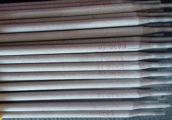
The welding electrode used for low carbon quenched and tempered steels should be of low hydrogen or ultra-low hydrogen type. Prior to welding, the electrodes must be dried according to the drying conditions specified by the manufacturer or the welding procedure specifications.
The dried electrodes should be immediately stored in a low-temperature and dry electrode holding oven for convenient access. Table 5-11 provides examples of welding electrodes for shielded metal arc welding, filler wires for gas metal arc welding, and shielding gases used for low carbon quenched and tempered steels.
Table 5-11: Examples of Welding Materials Selection for Low Carbon Quenched and Tempered Steels
Welding method/Grade
Shielded Metal Arc Welding (SMAW)
Submerged Arc Welding (SAW)
Gas Metal Arc Welding (GMAW)
Shielded Metal Arc Welding (SMAW)
14MnMoVN
J707 J857
H08Mn2MoA
H08Mn2NiMoVA
In conjunction with HJ350
H08Mn2NiMoA
In conjunction with HJ250
H08Mn2SiH08Mn2Mo
14MnMoNbB
J857
H08Mn2MoA
H08Mn2NiCrMoA
HJ350
H10Mn2MoA
H08Mn2Ni2CrMoA
In conjunction with HJ360HJ431
WCF-62
New 607CF
CHE62CF(L)
H08MnSiMo
Mn-Ni-Mo series
4. Key Points of Welding Process
(1) Pre-welding Preparation
Pre-welding preparation involves three aspects: preparation of welding groove, drying treatment of welding materials, and preheating.
1) Preparation of welding groove
Proper joint design, good groove processing, assembly, and welding quality are essential to ensure the excellent performance of low carbon low alloy quenched and tempered steels. When designing the joint, consideration should be given to the convenience of welding operations and post-weld inspections.
Incorrect placement of welds can lead to defects such as abrupt changes in cross-section, incomplete penetration, lack of fusion, undercut, and weld protrusion, as well as causing stress concentration.
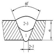
Generally, a butt joint is more suitable than a fillet joint as the latter has a higher stress concentration factor and significant notch effect. Additionally, butt joints are more convenient for radiographic or ultrasonic testing. U-shaped or V-shaped grooves are preferred, and double V-shaped or double U-shaped grooves can be used to reduce welding stress.
The grooves for low carbon low alloy quenched and tempered steels can be cut by gas cutting, but the hardened layer on the cut edge should be eliminated through heating or mechanical processing. When the plate thickness is less than 100mm, preheating is not necessary before cutting. For plate thicknesses ≥ 100mm, preheating at 100-150°C should be performed before cutting. For steels with higher severity levels, mechanical cutting or plasma arc cutting is preferred.
2) The welding materials should be dried according to the specified requirements
3) Preheating
In order to prevent cold cracking, preheating is often required when welding low carbon low alloy quenched and tempered steels. Generally, a relatively low preheating temperature (≤200°C) is used for welding low carbon low alloy quenched and tempered steels. When the preheating temperature is too high, it is not necessary for preventing cold cracking and can lead to significant embrittlement in the heat-affected zone. The minimum preheating temperature and interpass temperature for several low carbon low alloy quenched and tempered steels are listed in Table 5-12.
The welding heat input not only affects the performance of the heat-affected zone but also affects the performance of the weld metal. For many weld metals, a needle-like ferrite structure is required to achieve a combination of strength and toughness, and this structure can only be obtained under relatively fast cooling conditions. To avoid excessive heat input, it is not recommended to use large-diameter welding electrodes or filler wires.
Whenever possible, multi-pass narrow weld beads should be used instead of using the oscillation technique, as this not only improves the toughness of the heat-affected zone and weld metal but also reduces welding distortion. Carbon arc gouging can be used to clean the weld root, but strict control of the heat input is necessary. After carbon arc gouging, the gouged surface should be properly ground and cleaned before welding.
After welding a butt joint, it is necessary to grind down the excess height to ensure sufficient fatigue strength of the joint. Fillet joints tend to have stress concentration, which lowers the fatigue strength. Mechanical grinding, TIG re-melting, or hammer peening at the toe of the fillet weld can improve the fatigue strength of fillet joints, but the appropriate grinding, re-melting, or peening techniques must be selected.
(3) Post-Weld Heat Treatment
Most low carbon low alloy quenched and tempered steel welded components are used in the as-welded condition unless the following conditions require post-weld heat treatment:
1) Insufficient toughness of the steel after welding or cold working.
2) High precision machining is required after welding, and dimensional stability of the structure must be ensured.
In post-weld heat treatment of many precipitation-hardened low carbon low alloy quenched and tempered steels, stress relief cracks may occur in the heat-affected zone. To prevent the formation of stress relief cracks, measures such as lowering the annealing temperature, proper preheating, or post-weld heat treatment should be taken during welding.
2. Welding of Medium Carbon Quenched and Tempered Steels
1. Welding Characteristics of Medium Carbon Quenched and Tempered Steels
(1) Performance of Medium Carbon Quenched and Tempered Steels
Medium carbon quenched and tempered steels have a higher carbon content (generally ranging from wC=0.25% to 0.50%) and contain various alloying elements such as Mn, Si, Cr, Ni, Mo, and B, V, Ti, Al, etc., to ensure hardenability and prevent temper brittleness. These steels exhibit excellent comprehensive properties in the quenched and tempered condition, with yield strengths ranging from 880 to 1176MPa.
However, the hardenability of these steels is relatively high, which affects the welding characteristics. 40Cr is a widely used chromium quenched and tempered steel known for its good mechanical properties and high hardenability. It has high fatigue strength and is commonly used in manufacturing important components that operate under alternating loads, such as gears and shafts encountered during welding.
35CrMoA and 35CrMoVA steels belong to the Cr-Mo steel system, which are medium carbon quenched and tempered steels with good strength and toughness matching. These steels are mainly used in the manufacturing of gas turbine impellers, main shafts, and generator rotors, among others.
(2) Welding Characteristics of Medium Carbon Quenched and Tempered Steels
Medium carbon quenched and tempered steels have different welding characteristics compared to low carbon low alloy quenched and tempered steels. After welding, the quenched microstructure of medium carbon quenched and tempered steels is hard and brittle high carbon martensite. They are highly sensitive to cold cracking, and if not subjected to post-weld heat treatment, the performance of the heat-affected zone may not meet the requirements of the original base metal.
Therefore, these steels are generally welded in the annealed state, and post-weld quenching and tempering treatment is required to obtain uniformly welded joints with the desired performance.
However, in some cases, welding in the quenched and tempered state is necessary, and the deterioration of the heat-affected zone performance in such cases is difficult to resolve. The application of medium carbon quenched and tempered steels in welded structures is not as widespread as that of hot rolled and normalized steels and low carbon quenched and tempered steels.
1) Embrittlement and Softening in the Heat-Affected Zone
Due to the higher carbon content and multiple alloying elements in medium carbon quenched and tempered steels, the starting temperature (Ms point) for the transformation from austenite to martensite is relatively low during rapid cooling. This results in the formation of high hardness martensite in the heat-affected zone, leading to embrittlement.
If the steel is welded in the quenched and tempered state without subsequent tempering treatment, the heat-affected zone is heated to a temperature above the tempering temperature, resulting in a softening zone with lower strength and hardness compared to the base metal. This softening zone can become a weak area that reduces the strength of the joint.
2) Welding Cracks
Medium carbon quenched and tempered steels have a high susceptibility to both hot cracking and cold cracking, and measures need to be taken to eliminate their contributing factors.
The heat-affected zone of medium carbon quenched and tempered steels is prone to the formation of hard and brittle martensite. They are highly sensitive to hydrogen-induced cold cracking.
To prevent the occurrence of hydrogen-induced cold cracking when welding medium carbon quenched and tempered steels, it is important to use low hydrogen or ultra-low hydrogen welding materials and welding processes. Preheating before welding and timely post-weld heat treatment are commonly used to prevent cold cracking.
Due to the high carbon and alloy element content in medium carbon quenched and tempered steels, there is a wide temperature range between the solidus and liquidus temperatures during the solidification of the weld pool.
This leads to a significant tendency for solidification cracking. To prevent the formation of solidification cracks, it is recommended to use welding materials with low carbon, low sulfur, and low phosphorus. In terms of welding technique, attention should be paid to fully filling the arc crater.
2. Selection of Welding Methods and Welding Materials
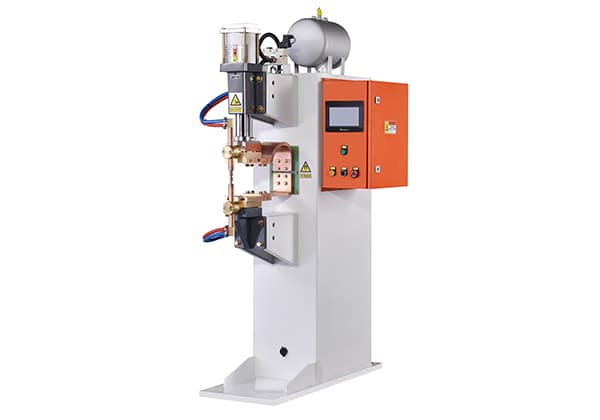
Commonly used welding methods for medium carbon quenched and tempered steels include tungsten inert gas (TIG) or helium arc welding, gas metal arc welding (GMAW), submerged arc welding (SAW), shielded metal arc welding (SMAW), and resistance spot welding.
Tungsten inert gas (TIG) or helium arc welding provides a low hydrogen content in the weld and is suitable for welding thin and highly constrained components. GMAW can use shielding gases such as CO2, Ar+CO2, or Ar+O2. GMAW produces welds with low hydrogen content, which helps reduce the possibility of cold cracking in medium carbon quenched and tempered steels.
SAW is commonly used for components that undergo post-weld tempering treatment. It is important to select the appropriate combination of wire and flux, using neutral or mildly basic fluxes to ensure that the post-weld heat-treated weld metal has satisfactory strength, ductility, and toughness.
Currently, SMAW is the most widely used welding method for medium carbon quenched and tempered steels. Low hydrogen or ultra-low hydrogen electrodes should be selected for SMAW. Several recommended electrodes are listed in Table 5-13.
1) Preparation of Grooves: The welding grooves for medium carbon quenched and tempered steels should be machined using mechanical methods to ensure assembly accuracy and avoid the formation of quenched microstructure caused by thermal cutting. Prior to welding, the base metal and welding materials should be thoroughly cleaned.
2) Drying of Electrodes and Flux: The electrodes and flux should be dried thoroughly before use, and measures should be taken to prevent moisture absorption during the welding process.
3) Preheating: In order to prevent hydrogen-induced cold cracking, except for thin-walled shells and other welded components with low restraint and simple structures, preheating is generally required when welding medium carbon quenched and tempered steels. The preheating temperature and interpass temperature can be controlled between 250 and 300°C.
(2) Determination of Welding Heat Input and Welding Technique
It is recommended to use lower heat input parameters for welding medium carbon quenched and tempered steels. High heat input will result in a wide and coarse-grained heat-affected zone, increasing the tendency for embrittlement. High heat input also increases the possibility of heat cracking in the weld and heat-affected zone. For components welded in the quenched and tempered state without subsequent tempering treatment, high heat input will increase the degree of softening in the heat-affected zone.
(3) Post-Weld Heat Treatment
To prevent hydrogen-induced cold cracking, post-weld heat treatment should be performed in a timely manner. If it is difficult to perform immediate tempering treatment, intermediate annealing or holding at a temperature above the preheating temperature can be done to eliminate diffused hydrogen and soften the heat-affected zone. Intermediate annealing also helps in stress relief.
3. Typical Welding Example of Common Alloy Structural Steels
1. Typical Welding Example of Hot Rolled and Normalized Steels
1) A company manufactures a rich/lean absorption heat exchanger, with the main material being 16MnR. The longitudinal weld seam of the shell is a butt joint with an asymmetric X-shaped groove. Submerged arc welding is used, and the specific welding procedure is shown in Table 5-14.
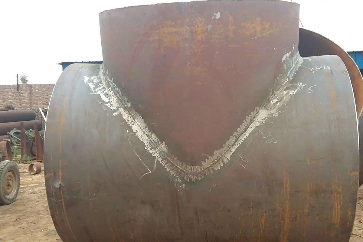
3) For the same equipment mentioned above, the welding seam between the large header and the internal head is a corner joint. The material is 16MnR with a thickness of 82.5mm and 38mm. It requires a K-shaped groove and falls under the category of medium-thick plate welding.
The preheating temperature for the welding area and its vicinity should be 100℃. The interlayer temperature during the welding process should be maintained between 100-250℃. After welding, it needs to be heated to 620℃ and held for 2 hours for stress relief annealing treatment. Please refer to Table 5-16 for specific welding process details.
Table 5-16: Welding Process Card for K-shaped Groove Corner Joint
Welding Process Card for Joints
Number
Joint Diagram
Base Material Material
16MnR
16MnR
Base Material Thickness
82.5mm
38mm
Welding Position
Flat Welding
Welding Technique
Straight Welding, Multiple Pass Welding
Preheating Temperature
100℃
Interlayer Temperature
≤100~250℃
Welding Sequence
1
Check groove dimensions and surface quality
2
Clean the groove and surrounding area from oil and other dirt
3
Perform tack welding using the first layer welding process from the outside, with a length of 30-50mm
4
Weld inner layers 1-6
5
Grind the root pass by carbon arc gouging from the outside, followed by grinding with a grinding wheel
6
Weld outer layers 7-16
7
Clean slag and spatter after welding
8
Perform visual inspection
9
Perform non-destructive testing
10
Perform post-weld heat treatment
Welding Specification Parameters
Passes
Welding Method
Welding Material Grade
Welding Material Specification
Types of Current and Polarity
Welding Current (Ampere)
Arc Voltage (Volt)
Welding Speed (mm/per pass)
Remarks
1
SMAW
J507
1.0
DCEP
150~180
22~24
150~200
2~16
SMAW
J507
5.0
DCEP
180~210
22~24
160~220
4) A chemical machinery manufacturing plant is producing a liquid chlorine storage tank. The main material is 16MnDR with a thickness of 22mm. The welding seam is for the closure of the cylindrical body, using a butt joint with an asymmetric X-shaped groove.
The welding process involves a combination of shielded metal arc welding (SMAW) and submerged arc welding (SAW). After welding, it requires a heat treatment at 620℃ for 1 hour to eliminate stress. Please refer to Table 5-17 for specific welding process details.
Table 5-17: Welding Process Card for Asymmetric X-shaped Groove Butt Joint
Welding Process Card for Joints
Number
Joint Diagram
Base Material Material
16MnDR
16MnDR
Base Material Thickness
22mm
22mm
Welding Position
Flat Welding
Welding Technique
Straight Welding Pass
Preheating Temperature
Room Temperature
Interlayer Temperature
≤150℃
Post-weld Heat Treatment
620℃,1h
Welding Sequence
1
Check groove dimensions and surface quality, groove surface 100% magnetic particle testing (MT)
2
Clean the groove and surrounding area from oil and other dirt
3
Perform tack welding using the first layer welding process from the outside, with a length of 30-50mm
4
Weld inner layers 1-4
5
Grind the root pass by carbon arc gouging from the outside, followed by grinding with a grinding wheel
6
Weld outer layers 5-6
7
Clean slag and spatter after welding
8
Perform visual inspection
9
Perform non-destructive testing
10
Perform post-weld heat treatment
Welding Specification Parameters
Passes
Welding Method
Welding Material Grade
Welding Material Specification
Types of Current and Polarity
Welding Current (Ampere)
Arc Voltage (Volt)
Welding Speed (mm/per pass)
Remarks
1
SMAW
J507GR
4.0
DCEP
140~170
22~24
150~200
2~4
SMAW
J507GR
5.0
DCEP
170~200
22~24
200~250
5~6
SAW
H10MN2 SJ101
4.0
DCEP
600~650
32~36
24~28m/h
5) As mentioned earlier, for the welding seam between the top nozzle flange and the pipe of the liquid chlorine storage tank, a butt joint is required with single-sided welding and double-sided formation.
Tungsten inert gas (TIG) welding is used for back sealing, and shielded metal arc welding (SMAW) is used for filling and capping. The groove is a V-shaped groove without a blunt edge. After welding, stress relief treatment is performed. Please refer to Table 5-18 for the welding process details.
Check groove dimensions and surface quality, groove surface 100% magnetic particle testing (MT)
2
Clean the groove and surrounding area from oil and other dirt
3
Perform tack welding using the first layer welding process from the outside, with a length of 5-10mm
4
Weld inner layers 1-3
5
Perform visual inspection
6
Perform non-destructive testing
7
Perform post-weld heat treatment
Welding Specification Parameters
Passes
Welding Method
Welding Material Grade
Welding Material Specification
Types of Current and Polarity
Welding Current (Ampere)
Arc Voltage (Volt)
Welding Speed (mm/per pass)
Remarks
1
GTAW
H10MnSi
2.5
DCEN
80~120
10~12
50~80
2~3
SMAW
J507GR
4.0
DCEP
140~170
22~24
140~180
2. Typical Example of Welding Low Carbon Low Alloy Quenched and Tempered Steel
A certain company is manufacturing the movable legs of a car crane, with material HQ80C. It uses a shielding gas mixture of argon and a welding wire of H08MnNi2MoA. Please refer to Table 5-19 for the welding process details.
Welding Process Card for Joints
Number
Joint Diagram
Base Material Material
HQ80C
HQ80C
Base Material Thickness
16mm
12mm
Welding Position
Flat Welding
Welding Technique
Straight Welding Pass
Preheating Temperature
100~125℃
Interlayer Temperature
100~125℃
Shielding GasGas Flow Rate (L/min)
Ar+CO2(20%)
Shielding GasGas Flow Rate (L/min)
10~15
Welding Sequence
1
Check groove dimensions and surface quality
2
Before assembly, perform shot blasting treatment to remove oxide scale, oil, and other dirt from the surface of the steel plate, groove, and surrounding area
3
Perform tack welding using the first layer welding process for positioning, with a length of 30-50mm
4
Weld the 4 inner corner welds, cleaning the root from the outside until the inner corner weld is exposed, then weld the outer corner welds
5
After welding, grind the welds and clean slag and spatter
6
Perform visual inspection
Welding Specification Parameters
Passes
Welding Method
Welding Material Grade
Welding Material Specification
Types of Current and Polarity
Welding Current (Ampere)
Arc Voltage (Volt)
Welding Speed (mm/per pass)
1
MAW
H08MnNi2MoA
l.2
DCEN
120~150
18~22
2~4
MAW
H08MnNi2MoA
1.2
DCEN
140~170
22-24
3. Typical Example of Welding Medium Carbon Quenched and Tempered Steel
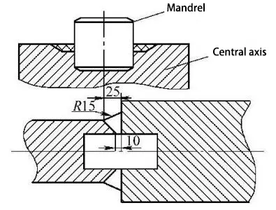
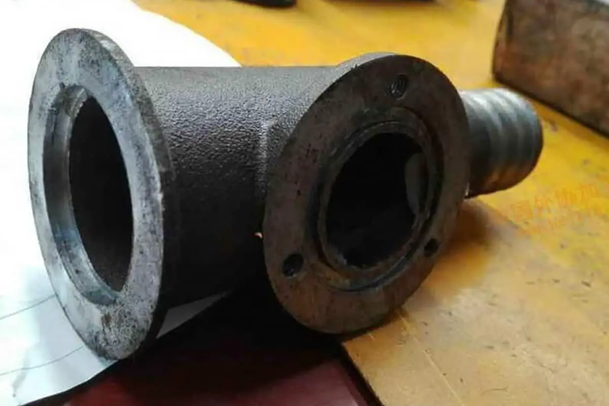
Repair of a broken shaft in a rolling mill, welding the shaft core to the intermediate shaft. The material is 37SiMn2MoV (similar to 42CrMo), and it is welded using shielded metal arc welding (SMAW) process. The welding electrode used is J607Ni. Please refer to the welding process details in the table.
Welding Process Card for Joints
Number
Joint Diagram
Base Material Material: 37SiMn2MoV (similar to 42CrMo)
37SiMn2MoV
37SiMn2MoV
Welding Position: Shaft core to intermediate shaft
Flat Welding
Welding Technique: Shielded Metal Arc Welding (SMAW)
Flat Welding
Preheating Temperature: As per welding procedure specifications
Straight Welding Pass, Multiple Passes with Multi-layer Pressure Welding
Interlayer Temperature: As per welding procedure specifications
300℃, within a 300mm range of the welding area
Post-weld Heat Treatment: As per welding procedure specifications
Clean the groove and surrounding area from oil and other dirt
3
Insert the shaft core into the intermediate shaft, and then place it in a pit-style heating furnace for preheating
4
During welding, ensure that the thickness of each layer of deposited metal is less than 2mm
5
Perform visual inspection
6
Perform hydrogen removal treatment at 350℃~400℃ for 2 hours. After sufficient insulation time, wrap the area within 300mm of the weld with insulation blanket
7
After cooling, perform liquid penetrant testing on the weld and surrounding base material, with no defects on the surface. After passing the inspection, process the end of the core shaft, assemble, and tighten after cooling. Apply uniform preheating to the area within 300mm of the weld, raising the temperature to 300℃. Welding requirements remain the same as mentioned above
8
Perform hydrogen removal treatment, following the same procedure as before
As the founder of MachineMFG, I have dedicated over a decade of my career to the metalworking industry. My extensive experience has allowed me to become an expert in the fields of sheet metal fabrication, machining, mechanical engineering, and machine tools for metals. I am constantly thinking, reading, and writing about these subjects, constantly striving to stay at the forefront of my field. Let my knowledge and expertise be an asset to your business.
What makes welding low-carbon quenched and tempered steel so challenging? This article explores the intricacies involved, from managing cold cracks to preventing embrittlement in the heat-affected zone. You'll learn key…
Imagine a world where metals fuse seamlessly with just a spark. This is the essence of spot welding, a technique that binds metal parts with precision and strength. In this…
Ever wondered how those sleek car bodies are welded together so seamlessly? This article dives into the world of spot welding machines, explaining their components, types, and applications across industries…
Have you ever wondered how complex machinery stays connected seamlessly? This article dives into the fascinating world of butt welding—a high-efficiency method used to join metals. You'll learn about its…
Choosing the right welding materials is critical for ensuring strong, durable welds. This guide explores the principles and best practices for selecting welding materials based on the performance requirements of…
How can welding carbon steel be both a common practice and a complex challenge? This guide explores the intricate world of carbon steel welding, covering types of carbon steel, their…
Why is welding carbon steel both an art and a science? Understanding the weldability of different carbon steels—from low to high carbon content—is crucial for ensuring strong, durable joints. This…
Have you ever wondered what makes welding stainless steel and heat-resistant steel so challenging? This article breaks down the complexities of welding these materials, from the unique properties of different…
Welding low-temperature steel requires a keen understanding of material properties, as extreme conditions can lead to brittle failures. The article discusses the technical requirements for low-temperature steel, emphasizing the importance…