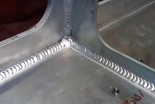
Welding copper and its alloys is a unique challenge due to their high thermal conductivity and tendency to crack. This article covers various welding techniques, materials, and preparation methods essential for achieving successful welds in copper and its alloys. Readers will learn about the specific weldability issues, pre-welding preparations, and the selection of appropriate welding methods and materials. By understanding these factors, one can enhance the performance and reliability of copper welds, crucial for applications in numerous industries.
Copper and copper alloys are widely used due to their unique and superior comprehensive properties. Copper and copper alloys have excellent electrical and thermal conductivity, high oxidation resistance, and resistance to corrosion in freshwater, saltwater, alkaline solutions, and organic chemicals.
However, they are susceptible to corrosion in oxidizing acids. Copper alloys have good cold and hot workability and higher strength. Copper and copper alloys have been widely used in industries such as electrical, electronics, chemical, food, power, transportation, aerospace, and defense.
There are various types of copper and copper alloys produced in industrial production, and most countries classify them based on their chemical composition. Copper and copper alloys can be classified into pure copper, brass, bronze, and white copper, among others.
Soft annealed pure copper is generally used for welding structures. Common types of pure copper include T1, T2, T3, T4, and deoxidized copper (oxygen-free copper) TU1, TU2, etc. Brass is a copper alloy primarily composed of zinc.
Commonly used brass and special brass alloys include H62, H68, H96, HPb59-1, HSn62-1, etc. Bronze originally referred to copper-tin alloys, but now it is commonly used to describe copper alloys that do not have zinc or nickel as the primary alloying element. Common types of bronze include tin bronze (QSn4-3), aluminum bronze (QAl9-2), silicon bronze (QSi3-1), etc.
In addition, copper alloys with nickel as the primary alloying element are referred to as white copper.
1. Weldability of Copper and Copper Alloys
The weldability of copper and copper alloys is comparatively poor, making it much more challenging to weld compared to low carbon steel. The main difficulties are observed in the following aspects:
(1) Poor weld formation capability:
When welding copper and most copper alloys, it is prone to difficulties in achieving fusion, incomplete penetration of the joint, and poor surface formation. This is mainly due to the high thermal conductivity of copper, with thermal conductivity of copper and most copper alloys being 7 to 11 times greater than that of ordinary carbon steel.
As a result, heat is rapidly dissipated from the welding zone. The thicker the workpiece, the more severe the heat dissipation. Although copper has a lower melting point and specific heat capacity compared to iron, it is still challenging to reach the melting temperature in the welding zone, making it difficult for the base metal and filler metal to fuse.
Additionally, the excellent thermal conductivity of copper leads to a broader heat-affected zone, which can result in significant deformation when the workpiece has low rigidity. Conversely, when the rigidity is high, it can cause substantial welding stress within the workpiece.
Poor surface formation in copper and copper alloys is mainly attributed to the fact that the surface tension during melting is one-third that of steel, and the fluidity is 1 to 1.5 times greater than that of steel, making it more susceptible to metal loss during melting.
Therefore, when welding pure copper and most highly conductive copper alloys, in addition to using high-power and high-energy density welding methods, it is also necessary to incorporate varying degrees of preheating. It is not permissible to use single-sided welding without support, and when performing single-sided welding, a backing plate must be added to control the formation of the weld joint.
(2) High susceptibility to heat cracking in welds and heat-affected zones:
The tendency for heat cracking in welds is related to the influence of impurities in the weld and is also influenced by the stresses generated during the welding process. Oxygen is a common impurity found in copper, and it has a significant impact on the tendency for heat cracking in welds.
At high temperatures, copper reacts with oxygen in the air to form Cu2O. Cu2O is soluble in liquid copper but not in solid copper, forming a low-melting-point eutectic. Impurities such as Bi and Pb in copper and copper alloys have low melting points.
During the solidification process of the weld pool, they form low-melting-point eutectics that distribute between dendrites or at grain boundaries, causing significant thermal brittleness in copper and copper alloys. When the weld is in the solid-liquid phase, the low-melting-point eutectics in the heat-affected zone re-melt under the influence of welding stresses, resulting in heat cracks.
Copper and copper alloys have relatively high linear expansion coefficients and shrinkage rates, and they also exhibit strong thermal conductivity. When welding, high-power heat sources are required, resulting in a wider heat-affected zone. As a result, the welded joints experience significant internal stresses, which is another factor that leads to cracking in copper and copper alloy welds.
Furthermore, when welding pure copper, the weld metal consists of a single-phase structure. Due to the high thermal conductivity of pure copper, the weld tends to form coarse grains. This further exacerbates the formation of heat cracks.
Therefore, to prevent the formation of heat cracks when using fusion welding to weld copper and copper alloys, the following metallurgical measures should be taken:
1) Strictly control the content of impurities (such as oxygen, bismuth, lead, sulfur, etc.) in copper.
2) Enhance the deoxidation capability of the weld by adding alloying elements such as silicon, manganese, phosphorus, etc., to the welding wire.
3) Select welding materials that can obtain a duplex structure, which disrupts the continuity of low-melting-point eutectic films and changes the direction of columnar grains.
4) Implement measures such as preheating and slow cooling to reduce welding stresses, minimize root gap size, and increase root pass dimensions to prevent crack formation.
(3) Susceptibility to porosity formation:
When fusion welding copper and copper alloys, the tendency for the formation of porosity is much more significant compared to low carbon steel. To reduce and eliminate porosity in copper welds, the main measures are to reduce the sources of hydrogen and oxygen and to preheat to prolong the existence time of the molten pool, making it easier for gases to escape.
Using welding wires with strong deoxidizers such as aluminum, titanium, etc. (which can also remove nitrogen and hydrogen) or adding elements like aluminum and tin to copper alloys can yield good results in terms of deoxidation.
During the fusion welding process of copper and copper alloys, the weld joints experience severe grain growth, evaporation and burn-off of alloying elements, as well as infiltration of impurities, leading to a decrease in mechanical properties, electrical conductivity, and corrosion resistance of the welded joints.
1) Significant decrease in ductility:
The weld and heat-affected zone experience grain coarsening, and various brittle low-melting-point eutectics appear at grain boundaries, weakening the metal’s bonding strength and significantly reducing the ductility and toughness of the joint. For example, when using pure copper welding electrodes for arc welding or submerged arc welding, the elongation of the joint is only about 20% to 50% of the base material.
2) Decrease in electrical conductivity:
The addition of any element to copper will decrease its electrical conductivity. Therefore, the melting of impurities and alloying elements during the welding process will to some extent deteriorate the electrical conductivity of copper joints.
3) Decreased corrosion resistance:
The corrosion resistance of copper alloys is achieved through alloying with elements such as zinc, manganese, nickel, aluminum, etc. The evaporation and oxidation of these elements during the fusion welding process will to some extent reduce the corrosion resistance of the joint. The generation of welding stresses also increases the risk of stress corrosion.
Measures to improve joint performance mainly involve controlling the content of impurities, reducing alloy burn-off, and performing heat treatment to modify the microstructure of the weld. Minimizing the heat input during welding and applying stress relief treatment after welding are also beneficial.
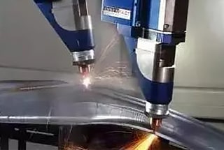
2. Selection of Welding Methods
Currently, there are many welding methods available for copper and copper alloys. Commonly used welding methods include gas welding, shielded metal arc welding, tungsten inert gas (TIG) welding, consumable electrode argon arc welding, and submerged arc welding.
The selection of welding methods should be based on the composition, thickness, structural characteristics, and performance requirements of the material being welded.
Copper is the metal with the best thermal conductivity among commonly used welding metals. Therefore, welding copper and its alloys require high-power and high-energy density welding methods.
Higher thermal efficiency and more concentrated energy are preferred. Different material thicknesses have different adaptability to various welding methods.
For example, thin plates are best suited for TIG welding and gas welding. Medium and thick plates are more suitable for submerged arc welding, consumable electrode argon arc welding, and electron beam welding. For thick plates, MIG welding and shielded metal arc welding are recommended.
3. Selection of Welding Materials
1) Welding Wire:
In addition to meeting general process and metallurgical requirements, the welding wire for welding copper and copper alloys should mainly control impurity content and improve deoxidation capability to avoid the formation of heat cracks and porosity.
For welding pure copper, deoxidizing elements such as Si, Mn, P are primarily added to the welding wire. Commonly used welding wires include high-purity copper welding wire HSCu, which is often used in gas welding along with solvent CJ301, and in submerged arc welding along with flux HJ431.
2) Welding Electrodes:
Arc welding electrodes for copper can be divided into copper and bronze types, with bronze electrodes being more commonly used. Due to the tendency of zinc in brass to evaporate, copper electrodes are rarely used for arc welding.
In such cases, bronze electrodes can be used. Commonly used copper electrodes include pure copper electrode T107 and silicon bronze electrode T207.
4. Pre-Welding Preparation
The requirements for pre-treatment of copper and copper alloy weldments are relatively strict. The pre-weld cleaning of copper and copper alloys mainly involves removing oil and oxide films. Before removing the oxide film, clean the groove and impurities within a 30mm range on both sides of the joint using gasoline or acetone.
Then, clean the groove from oil contamination using a 10% sodium hydroxide solution at a temperature of 30-40℃, followed by rinsing with water. Immerse the joint in a 35%-40% nitric acid solution for 2-3 minutes, rinse with water again, and then dry it.
The removal of oxide films can be done through mechanical and chemical cleaning. For mechanical cleaning, use a pneumatic wire wheel or wire brush to polish the surface of the welding wire and weldment until a metallic luster is visible.
Chemical cleaning involves immersing the weldment in a mixed solution of 70mL/L HNO3, 100mL/L H2SO4, and 1mL/L HCl for cleaning, followed by neutralization with an alkaline solution, rinsing with clean water, and then drying with hot air.
5. Key Points of Welding Process
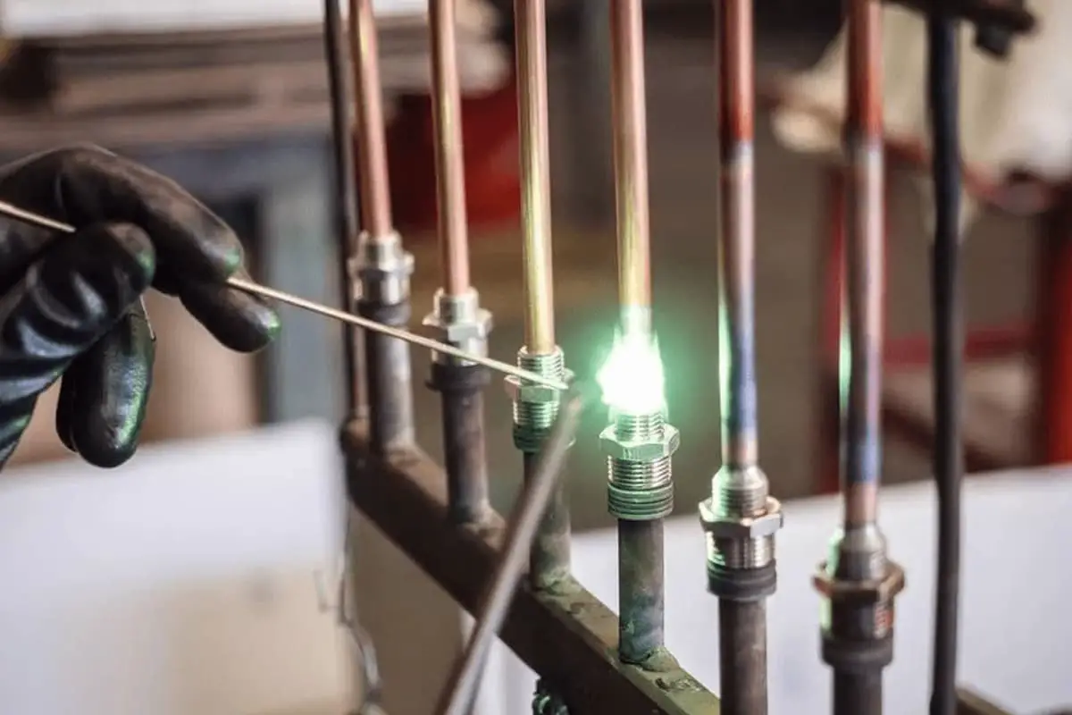
Gas Welding:
Gas welding is suitable for welding thin copper parts, repair of copper parts, or welding of non-critical structures.
Preheating is generally required for pure copper gas welding to prevent the occurrence of internal stresses, cracks, porosity, and incomplete penetration. The preheating temperature for thin sheets and small-sized weldments is around 400-500℃, while for thick and large weldments, the preheating temperature should be increased to 600-700℃. The preheating temperature for brass and bronze can be slightly lower.
2) Selection of welding parameters and welding technique: Copper has a high thermal conductivity, so the flame energy used for welding is generally 1-2 times higher than that used for welding carbon steel. When welding pure copper, a neutral flame should be strictly used.
An oxidizing flame can cause oxidation of the weld and burn-off of alloying elements. A carburizing flame can increase the hydrogen content in the weld and lead to the formation of porosity.
When gas welding thin sheets, the left-hand welding method should be used as it helps to suppress grain growth. When the thickness of the workpiece is greater than 6mm, the right-hand welding method is preferred as it allows for higher temperature heating of the base metal and provides better visibility of the molten pool, making the operation more convenient.
The movement of the welding torch should be as fast as possible, and each weld seam should not be interrupted randomly. It is preferable to complete each weld seam in a single pass.
When welding long seams, an appropriate allowance for shrinkage must be left before welding, and positioning should be done before welding. The segmented back-stepping method should be used during welding to reduce deformation.
For copper weldments subjected to stress or those of greater importance, post-weld hammering of the joint and heat treatment measures must be taken. After welding thin copper parts, the heat-affected zone on both sides of the weld should be immediately hammered.
For medium-thick plates above 5mm, they should be heated to 500-600℃ before hammering. After hammering, the workpiece should be heated to 500-600℃ and then rapidly cooled in water, which can improve the plasticity and toughness of the joint.
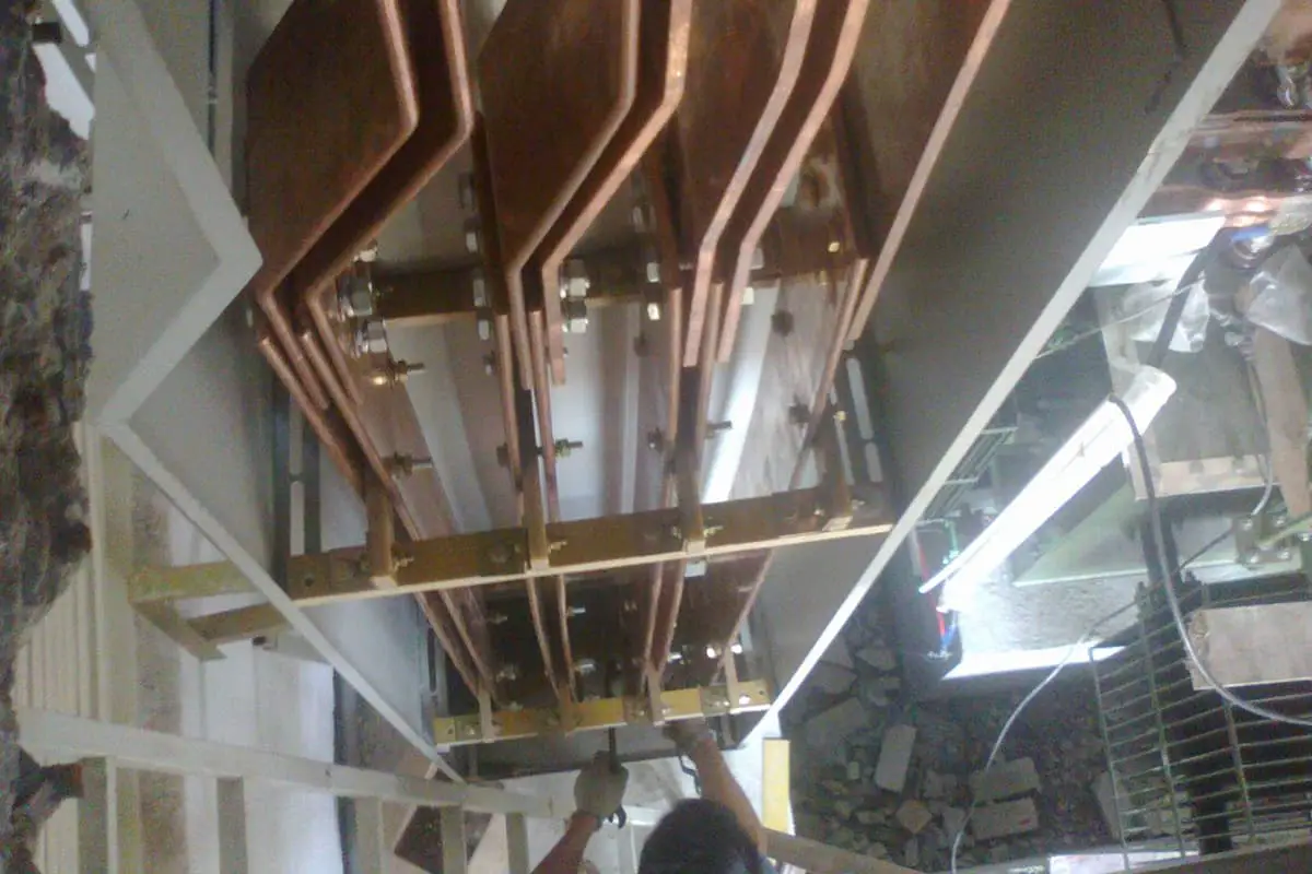
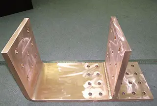
6. Typical Welding Examples of Commonly Used Copper and Copper Alloys
There is an electrode water jacket, made of deoxidized copper TU1. The electrode joint is welded using MIG welding, and the specific welding process is shown in Table 5-37.
Inspect the groove dimensions and surface quality.
2
Remove any oil or dirt from the groove and its vicinity. Clean the grease by using a 10% NaOH water solution at a temperature of 30~40℃, then rinse with clean water and dry. Remove the oxide film by grinding with a stainless steel wire wheel, then rinse with alkaline water, followed by rinsing with clean water and drying.
3
Perform tack welding for the first layer using an outer positioning welding technique. The length should be 100mm, and the distance between weld points should not exceed 300mm. If cracks appear in the tack weld seam, remove them and re-weld.
4
Splice the electrodes on a specially designed fixture. Preheat the workpiece using electric heating, with a preheating temperature of 500℃, and ensure that the interlayer temperature remains no lower than 500℃.
5
Start welding from the outside to avoid the formation of weld beads on the inside of the weld seam. Ensure the roundness of the electrode inner circle and the smoothness of the inner surface.
As the founder of MachineMFG, I have dedicated over a decade of my career to the metalworking industry. My extensive experience has allowed me to become an expert in the fields of sheet metal fabrication, machining, mechanical engineering, and machine tools for metals. I am constantly thinking, reading, and writing about these subjects, constantly striving to stay at the forefront of my field. Let my knowledge and expertise be an asset to your business.
What makes copper busbar welding so crucial yet challenging? This article delves into the high conductivity, thermal properties, and specific welding techniques required for copper busbars in power construction. From…
Imagine fusing two very different metals seamlessly. This article unveils seven effective methods for welding brass and red copper, metals known for their unique properties and challenges. From gas welding…
Ever wondered how skyscrapers stand tall or cars stay welded together? This blog uncovers the magic behind electric welding machines. Learn about top manufacturers like Lincoln Electric and Miller Welds,…
Have you ever wondered how the sleek cars, sturdy bridges, and advanced airplanes of today are built? This article explores six cutting-edge welding technologies that are revolutionizing manufacturing, from laser…
Welding aluminum alloys presents unique challenges due to their low melting point and high thermal conductivity. This article dives into various welding methods, such as TIG, MIG, and plasma arc…
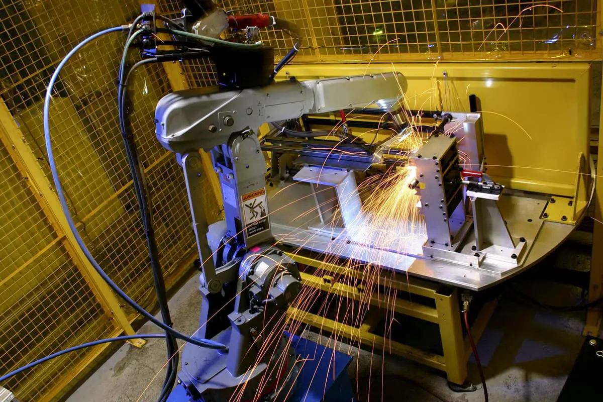
During the welding production process, there are many reasons why a welding robot might burn the contact tip. Observable symptoms indicating frequent replacement of the contact tip include: wear at…
Welding is the backbone of modern manufacturing, but with so many methods available, how do you choose the right one for your project? In this blog post, we'll dive into…
Imagine a world where metals fuse seamlessly with just a spark. This is the essence of spot welding, a technique that binds metal parts with precision and strength. In this…
Imagine welding without gas – chaotic and weak. Welding gas is the silent champion, essential for shielding welds from contaminants, stabilizing the arc, and ensuring strong joints. This article explores…