How does 9Ni steel’s remarkable low-temperature toughness enhance its utility in critical industries like aerospace and marine engineering? The welding process of 9Ni steel, especially crucial for oil and gas applications, ensures strength and resistance to sulfide stress corrosion. This article explores the meticulous techniques and preventive measures necessary for welding 9Ni steel, providing insights into its properties, challenges, and solutions to avoid defects and ensure quality in extreme conditions. By mastering these welding practices, engineers can achieve durable and reliable joints in demanding environments.
Due to its excellent comprehensive properties and cost advantages, 9Ni steel is extensively utilized in various industries such as aerospace, petroleum, chemical, shipbuilding, marine engineering, electric power, metallurgy, machinery, nuclear energy, and more.
This post focuses on the construction of the oil and gas module project located under salt. In this project, the 9Ni steel is required to possess not only high strength and outstanding low-temperature toughness but also SSC (sulfide stress corrosion) resistance under specific oil and gas conditions. Therefore, the welding process of the 9Ni steel pipe system is under study.
2. Weldability analysis of 9Ni Steel
9Ni steel was developed by Inco in the United States during the 1940s. It is a medium-alloy steel containing 9% nickel, enabling it to exhibit low-temperature toughness of up to -196 ℃.
When compared to austenitic stainless steel and austenitic iron-nickel alloy, 9Ni steel has a higher strength and lower cost. Additionally, 9Ni steel boasts better comprehensive mechanical properties than aluminum alloy.
However, the material is prone to magnetization and is difficult to demagnetize. Additionally, welding technology requires stringent adherence to specific requirements.
This article will analyze the weldability of 9Ni steel.
Cold cracking is unlikely to occur when welding 9Ni steel with high nickel or medium nickel electrodes. However, when low nickel and high manganese electrodes are used with improper welding conditions such as low line energy and damp electrodes, cold cracking may occur. The generation of cold cracks has three aspects:
2.1.1 The appearance of a hardened layer in the fusion zone. Although the carbon content of 9Ni steel is not high (≤ 0.10%), a hardened structure may be produced if welding material with high carbon content is selected. This is due to an increase in carbon content resulting from fusion and diffusion.
2.1.2. The presence of too much hydrogen, which accumulates in the hardened layer due to impurities (such as oil and rust) near the weld groove.
2.1.3. The stress concentration of welded joints, which includes structural stress, thermal stress, and restraint stress.
2.2 . Thermal crack
When welding 9Ni steel, hot cracks can occur regardless of whether a high nickel type, medium nickel type, or low nickel high manganese type electrode is used. However, the use of a high nickel type electrode can result in the most severe cracks.
This is due to the fact that the alloy contains elements such as S and P, which can easily form low melting point eutectics with nickel. As a result, intergranular segregation can occur. Furthermore, elements such as C and Si can also promote the segregation of S and P.
In particular, when the structure is in a pure austenite state, the distribution of impurities on the grain boundary can be continuous.
2.3 Low temperature toughness reduction
The reduction of low-temperature toughness is mainly influenced by two factors:
2.3.1 Influence of Welding Materials:
The chemical composition of the weld metal and fusion zone is related to the welding materials used. If the welding materials have a high carbon content, or if the Ni Cr equivalent matching of the welding materials and the base metal after fusion falls into the area containing martensite in the stainless steel organization chart, the low-temperature toughness will be reduced.
2.3.2 Welding Line Energy and Interlayer Temperature:
Welding line energy and interlayer temperature can alter the peak value and temperature of the welding thermal cycle, thereby affecting the metallographic structure of the heat-affected zone. If the peak temperature is too high, it can lead to a reduction in reverse austenite and the formation of coarse bainite, both of which can result in reduced low-temperature toughness.
2.4 Magnetic blow partial
Magnetic blow partials can cause poor weld fusion and significantly affect the quality of welding.
9Ni steel has high permeability and remanence induction intensity, making it susceptible to magnetic blow partials during welding.
Generally, when using the DC method (manual DC arc welding, manual DC argon arc welding, etc.) for backing welding of magnetic pipes, magnetic blow partials are common at the initial welding position of the backing weld, but they are not typically present during filling and cover welding.
The causes of cold cracks in welding are stress, hardened structure, and the diffusive hydrogen content of the weld metal. The generation of thermal cracks is related to stress, impurities, and chemical composition. Therefore, selecting the appropriate welding materials is critical.
After analyzing the properties of different welding materials, it was found that nicrmo-3 welding material is highly advantageous for welding 9Ni steel.
3.1.1 The linear expansion coefficient of nickel alloy in nicrmo-3 welding material is similar to that of 9Ni steel at both room temperature and high temperature. This similarity helps avoid thermal stress caused by uneven expansion and contraction.
3.1.2 The Ni content of nicrmo-3 welding material is high, ranging from 55% to 65%, and the carbon content is similar to that of 9Ni steel. Both materials belong to the low-carbon type. Even with the dilution effect of the base metal, there is still a high enough austenite structure to avoid the formation of a hard and brittle martensite belt on the fusion line.
3.1.3 Nicrmo-3 welding material has the following characteristics: low carbon (carbon content ≤ 0.1%), a small “brittle temperature range” in the phase diagram of F-C alloy, high purity (S ≤ 0.03%, P ≤ 0.02%), and low hydrogen content. The use of nicrmo-3 welding material can thus provide the basic conditions needed to reduce the tendency of cold and hot cracks in 9Ni steel welds.
Therefore, under the strict control of diffusive hydrogen content, selecting nicrmo-3 welding material can effectively avoid the tendency of cold and hot cracks in the welding of 9Ni steel.
3.2 Guarantee of low temperature toughness of welded joints
Welded joints consist of the weld, fusion line, and heat-affected zone.
The low-temperature toughness of welded joints generally occurs in the weld metal, fusion zone, and coarse-grained zone.
The low-temperature toughness of weld metal is mainly influenced by the type of welding material used.
When welding 9Ni steel with materials that have the same composition as 9Ni steel, the weld metal’s low-temperature toughness is typically poor, primarily because of high oxygen content in the weld metal.
Therefore, Ni-based and Fe-Ni-based electrodes are usually employed for welding 9Ni steel.
When 9Ni steel is welded with nicrmo-3 welding material, the chemical composition and metallographic structure of each area differ.
The weld metal is austenitic and has excellent low-temperature toughness.
In the fusion zone, the welding material’s carbon content is essentially the same as that of 9Ni steel, with a Ni content of over 55%, effectively preventing carbon migration and avoiding a brittle structure in the fusion zone, thereby ensuring the fusion zone’s low-temperature toughness.
In the heat-affected zone, under the thermal cycle of a peak temperature above 1100 ℃, coarse martensite and bainite structures are generated, which reverse the reduction of austenite and decrease the low-temperature toughness.
Therefore, the line energy should be controlled as much as feasible, and multipass welding should be used to minimize high-temperature residence time.
Thus, when welding 9Ni steel with nicrmo-3 welding material, the welded joint’s low-temperature toughness is largely influenced by the welding heat input and the cooling rate of the weld metal’s crystallization process.
3.3. Methods to overcome magnetic bias blowing
3.3.1. Change the position of the grounding wire for the base metal:
To minimize the current loop formed by the current on the base metal, the grounding wire should be directly led near the groove or placed on the groove. It should not be connected to the base metal at a long distance.
3.3.2. Temporarily create several tack welds above the groove (not at the root of the groove) to short circuit the magnetic field on both sides of the groove. When priming to this position, use a grinder to remove the tack welds.
4. Test materials and methods
4.1. Test materials
9Ni steel (355.6mm in diameter and 50.8 mm in wall thickness) produced by Hengyang Valin Steel Pipe Co., Ltd. was used as the base material for the test.
See Table 1 for chemical composition and table 2 for mechanical properties.
Table 1 chemical composition of 9Ni steel pipe (wt%)
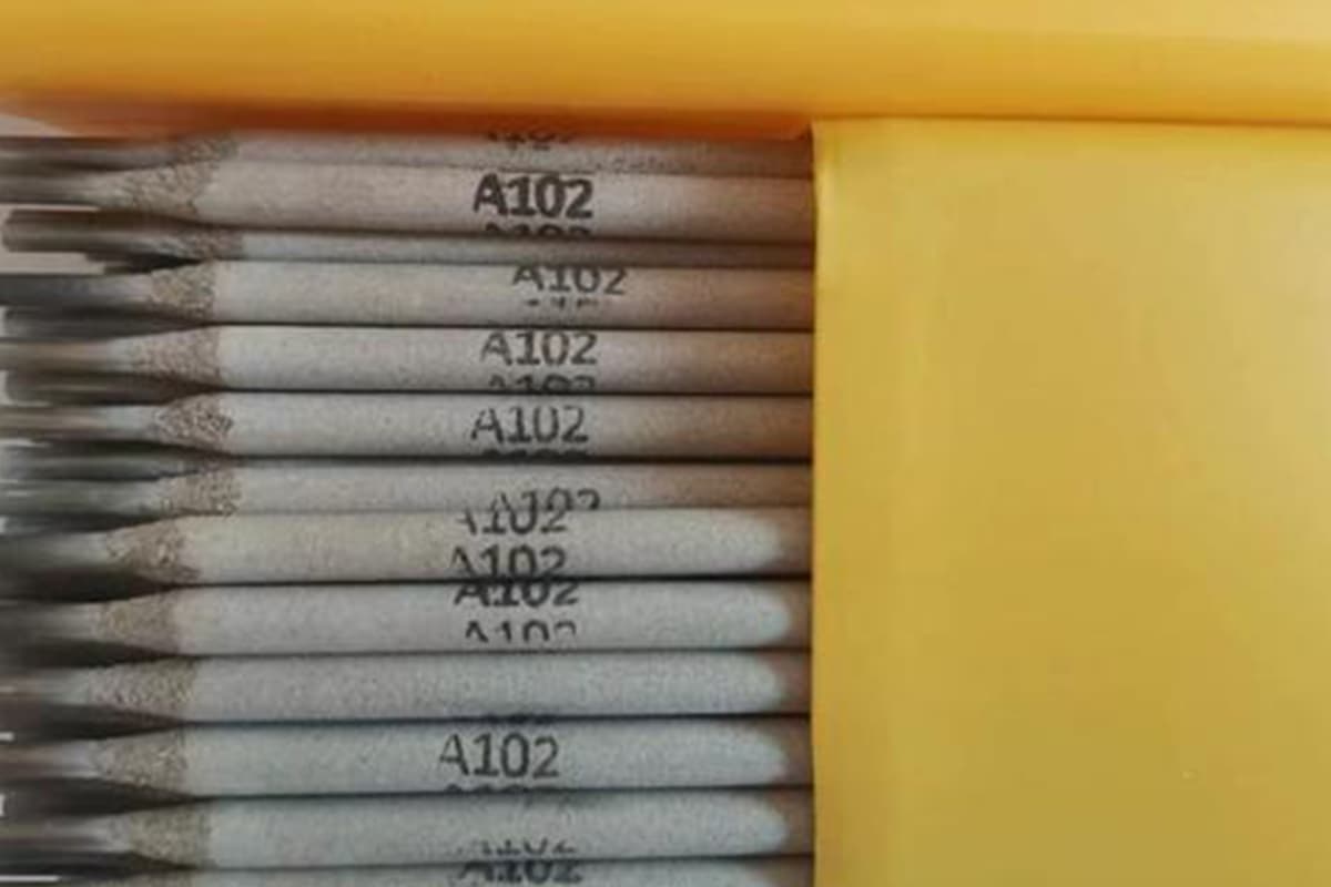
Based on the specific requirements of the product, tungsten argon arc welding (GTAW) is utilized for backing welding, while manual arc welding (SMAW) is employed for filling and capping welding. Additionally, nicrmo-3 welding material is used during the welding process.
See Table 3 for specific chemical composition.
Table 3 chemical composition of welding materials (wt%)
Type
C
Si
Mn
Cr
Mo
Cu
Ni
Mo
ERNiCrMo-3
0.01
0.04
0.03
0.004
0.004
22.2
64.3
9.3
ENiCrMo-3
0.02
0.36
0.4
0.005
0.006
22.7
63.6
8.8
5. Welding procedure qualification
5.1 Preparation before welding
5.1.1 The cutting and groove processing of 9Ni steel pipe should preferably use the mechanical processing method. However, gas cutting or plasma blanking and groove preparation can also be used.
The processed or cut groove must be polished.
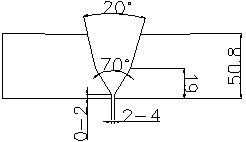
5.1.2 Due to the large wall thickness of the pipe used in this evaluation, it is necessary to design a suitable groove type.
Considering reducing the groove area and welding deformation, improving the welding efficiency, and reducing the consumption cost of Ni-based welding materials, it has been decided to adopt the groove type shown in Fig. 1. The groove should have a gap of 24mm and a blunt edge of 02mm.
5.1.3 Once the groove processing is completed, the appearance should be inspected to ensure that there are no cracks or delaminations. If any such defects are found, they must be repaired.
5.1.4 Mechanical methods and organic solvents must be used to clean the surface of the groove and the area within 20mm on both sides to remove oil, rust, metal chips, oxide film, and any other dirt on the surface.
Fig. 1 groove details
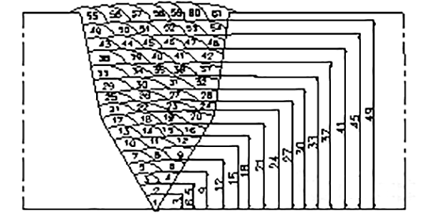
5.2 Welding sequence and weld bead layout
The backing layer has been welded using argon arc welding.
To ensure the formation of the root weld bead and avoid the burning through phenomenon during manual arc welding filling, at least two layers of backing welding must be applied, with a minimum weld thickness of 6mm, and filled using manual arc welding.
Please refer to Figure 2 for the welding layer arrangement sequence.
Fig. 2 weld bead layout
5.3 Welding process parameters
The heat input refers to the amount of energy received by the weld per unit length and is the primary factor that influences the welding thermal cycle. Therefore, controlling the heat input is essential to guarantee the mechanical properties and sulfide stress corrosion (SSC) resistance during testing.
5.3.1: As the melting point of weld metal that is welded with nickel-based welding materials is approximately 100℃ lower than that of 9Ni steel, it can easily cause defects, such as incomplete fusion between the groove edge and weld bead. Hence, it is prohibited to strike an arc haphazardly during the welding process, and the arc should not be struck outside the groove to prevent damaging the base metal.
5.3.2: While welding the arc, it is important to fill the crater and stay on the arc for a while to avoid crater cracks. In the case of crater cracks, immediate polishing is necessary.
5.3.3: To ensure the low-temperature toughness and SSC test results of 9Ni steel, the control of welding heat input is crucial, and the welding current should not be excessive. It is advisable to use fast multi-pass welding to minimize weld bead overheating and refine the grain through the reheating effect of multi-pass welding.
During multi-pass welding, the interlayer temperature should be regulated, and small heat input should be used for welding. The heat input should be controlled below 20KJ/cm. The interlayer temperature of multi-layer welding should be kept lower than 100℃ to avoid overheating of the joint.
6. Test results and analysis
6.1 Nondestructive testing
After welding, the test piece underwent a visual inspection, which revealed no undercut, surface pores, cracks, slag inclusions, or other defects in both the weld and heat-affected zone.
The weld reinforcement measured between 0.5 and 1.5mm, and the weld and base metal exhibited a smooth transition.
Radiographic inspection showed no cracks, incomplete fusion, incomplete penetration, slag inclusions, or other defects in the test piece, confirming that the quality of the welded joint meets the standard requirements.
6.2 Tensile test
During a tensile test, the tensile specimen is secured onto a WE-100 universal testing machine. Tensile stress is then applied to the specimen, causing axial elongation until it reaches its breaking point. This is the main indicator used to measure the strength of materials.
The results of the test are displayed in Table 5.
Table 5 tensile test results
Test piece No.
Tensile strength (MPA)
Fracture location
1
761
base metal
2
764
base metal
Based on the test results, it is evident that the tensile test meets the specification requirements.
6.3 Bending test
The bending test assesses the materials’ ability to withstand deformation.
Using the WE-100 universal testing machine, processed standard bending samples are tested.
To conduct the test, four side bending samples are taken according to the specifications, and a 63.5mm indenter diameter is used. The bending angle is set at 180°.
After the bending test, there should be no cracks or defects longer than 3mm in any direction on the surface of the samples.
Based on the results of the test, it meets the specification requirements.
6.4 Impact test
The purpose of the impact test is to determine the impact performance of a welded joint by measuring the amount of impact energy consumed per unit area at the point where the groove on the joint surface is broken. To conduct this test, an impact sample is placed on a JB-30B impact testing machine, which applies the impact load necessary to break the groove.
For this particular impact test, a Charpy impact is used at a temperature of -196 ℃. Samples are taken from a position approximately 1 to 2mm away from the weld surface.
The notch positions are located at various points along the joint, including the weld center, fusion line, fusion line 1mm, fusion line 2mm, and fusion line 5mm.
The test results are shown in Table 6.
Table 6 impact test results
Notch location
Single impact value (J)
Average impact value (J)
Weld center
89, 78, 76
81
Meld Line
80, 82, 76
79
Meld Line+1 mm
104, 91, 111
104
Meld Line+2 mm
78, 99, 85
87
Meld Line+5 mm
112, 98, 104
104
Based on the impact results, it can be seen that the impact values meet the specification requirements of (-196℃ ≥ 41J).
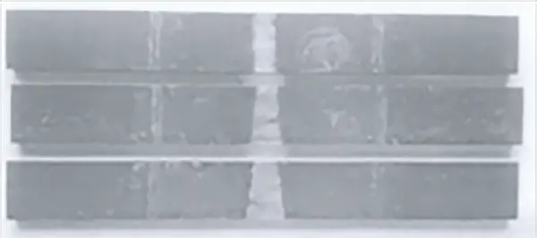
6.5 Macro and hardness test
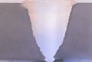
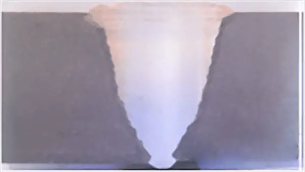
After conducting a macro section inspection of the weld, it was determined that the weld is fully welded without any cracks or other defects. Figure 3 shows the macro sample.
Fig. 3 macro sample photo
6.5.2 Measure the hardness of weld metal, heat affected zone and base metal of welded joints respectively.
The hardness values are shown in Table 7.
Table 7 hardness test results
Sampling Position
Hardness value (HV10)
Weld metal
219~247
Heat Affected Zone
253~290
Base metal
230~256
6.6. SSC (sulfide stress corrosion) test
Three standard plate-shaped samples were taken and filled continuously with a solution of 99.2% CO2, 0.8% H2S, and acetic acid (initial pH=3) at 25 ℃. The samples were then loaded with 80% yield strength using 4-point bending (σS=698 MPa) and soaked for 720 hours. It was observed that the samples did not break.
Upon examining the samples under a 10x magnifying glass, no cracks were detected. Furthermore, the sulfide stress corrosion test of this batch of samples met the standards specified (refer to Figure 4).
Fig. 4 surface morphology of compressive stress sample after immersion corrosion
7. Conclusion
7.1 With the use of argon tungsten arc welding for backing, manual arc welding for filling and covering, and the welding of 9Ni steel with ERNiCrMo-3 welding wire and ERNiCrMo-3 welding rod, high-quality welding joints can be achieved under appropriate welding process conditions.
7.2 The welding procedure qualification test has met all performance indexes and technical requirements. We have gained mastery in TIG backing, manual arc welding filling, and pipe system welding technology for 9Ni steel, which will provide valuable experience for guiding future production.
As the founder of MachineMFG, I have dedicated over a decade of my career to the metalworking industry. My extensive experience has allowed me to become an expert in the fields of sheet metal fabrication, machining, mechanical engineering, and machine tools for metals. I am constantly thinking, reading, and writing about these subjects, constantly striving to stay at the forefront of my field. Let my knowledge and expertise be an asset to your business.
How can welding stainless steel tanks be more efficient and precise? The double-side argon arc welding process is revolutionizing the industry by reducing spatter, minimizing deformation, and enhancing weld quality.…
Why is brazing stainless steel so challenging yet crucial? This article explores the key issues, from oxide film removal to temperature control, impacting the quality and durability of brazed joints.…
Have you ever wondered what makes welding stainless steel and heat-resistant steel so challenging? This article breaks down the complexities of welding these materials, from the unique properties of different…
Welding low-temperature steel requires a keen understanding of material properties, as extreme conditions can lead to brittle failures. The article discusses the technical requirements for low-temperature steel, emphasizing the importance…
Ever wondered what makes stainless steel welding so resilient? In this article, we'll explore the fascinating world of stainless steel welding rods, revealing how their unique compositions and properties make…
Have you ever wondered why welding stainless steel is considered both an art and a science? This guide unravels the complexities of stainless steel welding, covering the entire process from…
What determines whether two pieces of metal can be seamlessly joined? This article dives into the critical factors influencing the weldability of metal materials, from material composition to environmental conditions.…
What makes the right electrode and welding wire so crucial for a perfect weld? This guide delves into the specifics of various electrode and welding wire models, including their applications…
Ever wondered why some welds hold strong while others fail? This article uncovers the secrets behind welding rods, their types, and their critical role in ensuring durable welds. Learn how…