7 Steps to Complete the Production of Sheet Metal Products
Have you ever wondered how the intricate components of your everyday devices are made? This article demystifies the production process of sheet metal products, detailing the journey from initial drawing design to final packing and delivery. By the end, you’ll understand the essential steps, including laser processing, CNC stamping, bending, welding, and coating, that transform raw metal sheets into precise, functional parts. Dive in to gain insight into this vital manufacturing process!
Our common sheet metal processing consists of six main steps, which are described in detail below:
Design Drawing
Laser Processing / NC Stamping
Bending
Welding Forming
Electrostatic Powder Coating / Liquid Painting
Packing and Delivery
Steps To Complete The Production Of Sheet Metal Products
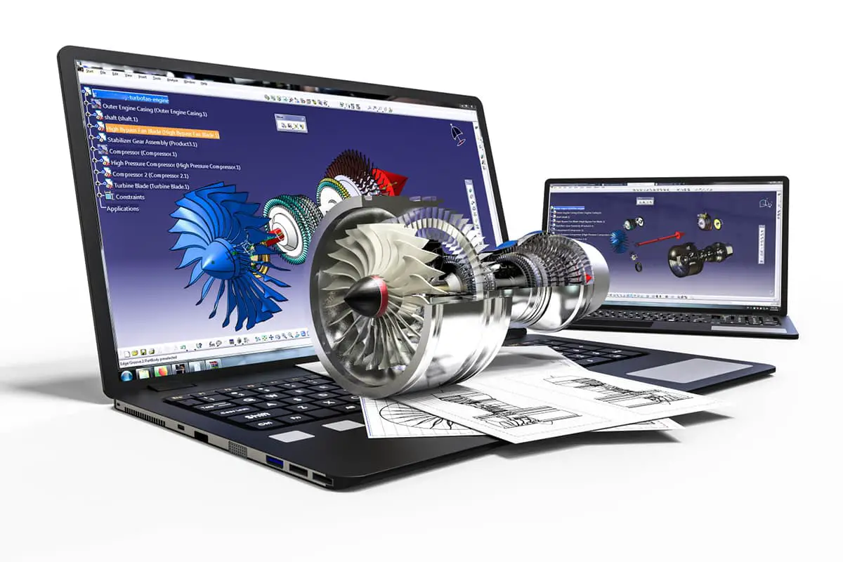
1. Drawing design
General customers provide either drawings or samples, which are then analyzed and designed by the company’s engineering team. This process results in the creation of both processing breakdown drawings and assembly drawings. These are then submitted to the production department for processing.
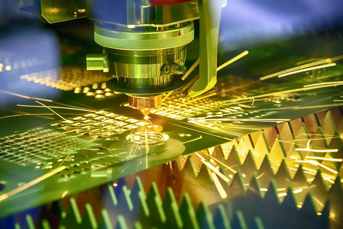
The laser cutting machine is capable of cutting carbon steel, stainless steel, and various other materials. The result is a smooth, neat, and accurate cut with a beautiful edge. This method is especially advantageous for workpieces with curved shapes and is an indispensable processing technique compared to traditional CNC stamping.
3. CNC stamping
The CNC Turret Punch is primarily used for products with a thin material thickness, usually less than 2.5mm. This method is well suited for sheet metal parts that require multiple holes or the need to use a specialized mold for processing. When the quantity of parts is large, CNC stamping has a cost advantage over other methods.
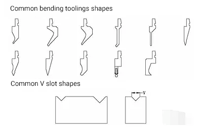
4. Bending
If the majority of the workpieces require bending after cutting, press brakes are necessary to complete the bending process. The CNC press brake is preferred because it is not only faster but also more accurate.
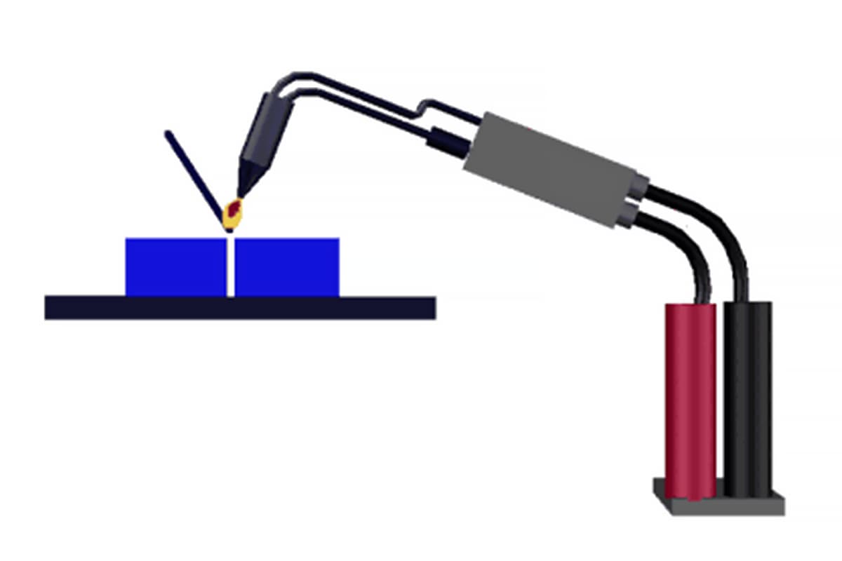
Generally, after the blanking process, the workpiece needs to be assembled and formed. There are various assembly methods, some of which use non-welding processes such as screws or rivets. For most mechanical shell sheet metal, welding molding is used and the company typically employs argon arc welding, touch welding, or carbon dioxide welding. After welding, the workpiece is polished to ensure its strength and enhance its appearance.
6. Electrostatic powder spraying
Electrostatic powder coating primarily targets carbon steel parts. The process involves several steps such as removing oil and rust, surface cleaning, phosphating treatment, electrostatic powder coating, and high temperature baking. The result is a beautiful surface that will remain rust-free for several years and is cost-effective.
In contrast, liquid paint is a different process that is typically used for large workpieces and is more convenient and cost-effective when transportation is not an option. Liquid painting is usually divided into two steps: application of primer and then paint.
7. Packing and delivery
Before packaging, a 100% inspection is conducted and the inspection data is provided. The delivery requirements and packing method are confirmed by the customer’s representative on site, and a record of this is created for the customer’s confirmation.
Process flow of sheet metal products
1. Sheet metal processing method:
(1) Non mold processing
The technology of sheet metal processing, which includes punching, laser cutting, shearing, folding, and riveting machines, is generally used for the production of samples or small batches with a higher cost.
(2) Mold processing
The use of fixed molds for sheet metal processing includes blanking molds and forming molds, and is mainly utilized for mass production with a lower cost.
The blanking of sheet metal can be achieved through several methods such as punching, laser cutting, shearing machine, die blanking, etc. Currently, CNC punching is the most commonly used method. Laser cutting is mainly utilized during the prototyping stage due to its high processing cost, while die blanking is often used for mass production.
Here, we will focus on the blanking of sheet metal using CNC punches. The CNC punch, also known as a turret punch, can perform various operations such as blanking, punching, drilling holes, and pressing bars. Its machining accuracy can reach +/- 0.1mm.
The following table shows the thickness of sheet metal that can be processed by CNC punching:
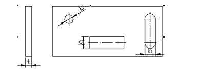
The small size requirement for punching depends on factors such as the shape of the hole, the mechanical properties of the material, and the thickness of the material (as illustrated in the following figure).
(2) The distance between holes and the distance between hole edges.
The small distance between the punching edge and the shape of the part is limited by both the shape of the part and the hole. If the punching edge is not parallel to the contour edge of the part, the minimum distance should not be less than the material thickness T. If it is parallel, the minimum distance should not be less than 1.5T (as illustrated in the following figure).
(3) Guidelines for drawing holes.
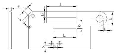
When drawing holes, the minimum distance between the drawing hole and the edge should be 3T. The minimum distance between two drawing holes should be 6T, and the safe minimum distance between the drawing hole and the inner bending edge should be 3T + R (where T is the sheet metal thickness and R is the bending radius).
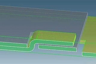
(4) Spacing requirements for drawing bending and deep drawing parts.
When drawing bending and deep drawing parts, a certain distance should be maintained between the hole wall and the straight wall (as illustrated in the following figure).
The bending sequence should follow the principles of bending from the inside to the outside, bending from small to large, bending special shapes first and then general shapes, and ensuring that the earlier processes do not interfere with the subsequent ones.
② Small Bending Radius of Bending Parts:
When material is bent, the outer layer of the fillet experiences stretching while the inner layer experiences compression. As the inner bending radius (R) decreases, the tensile and compression stresses increase. If the tensile stress of the outer fillet exceeds the material’s ultimate strength, cracks and fractures may occur. Therefore, the design of bending parts should avoid overly small bending radii.
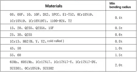
The minimum bending radii of common materials used by the company are shown in the following table:
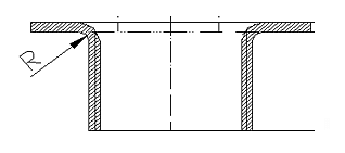
Table of Minimum Bending Radius of Bending Parts:
The bending radius refers to the inner radius of the bending part, and t is the wall thickness of the material.
(2) Sheet Metal Stretching
Sheet metal stretching is primarily accomplished through the use of several punches or a single punch and requires various drawing punches or dies. The shape of the drawn part should be as simple and symmetrical as possible, and it should be stretched as far as possible in one operation. If multiple stretching operations are necessary, it is acceptable for the surface to show traces of the stretching process. The stretching side wall can have a certain inclination as long as it meets assembly requirements.
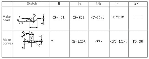
① Reinforcing Ribs – Adding reinforcing ribs to sheet metal parts increases structural rigidity.
Reinforcing Rib Structure and Size Selection:
② Louvers – Louvers are commonly used for ventilation and heat dissipation on various enclosures or casings.
③ Hole Flanging (Stretching Hole) – Hole flanging, also known as stretching holes, is used to create threads or to increase the rigidity of openings.
3. Welding
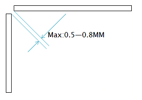
In the design of sheet metal welding structures, the welds and joints should be arranged symmetrically and the occurrence of convergence, aggregation, and overlap should be avoided. Secondary welds and joints can be interrupted while the main welds and joints should be connected.
Common welding methods used in sheet metal processing include electric arc welding and resistance welding.
In this section, we will mainly introduce the methods of connecting sheet metal during the processing stage, which include rivet riveting, welding (as previously described), hole riveting, and Tox riveting.
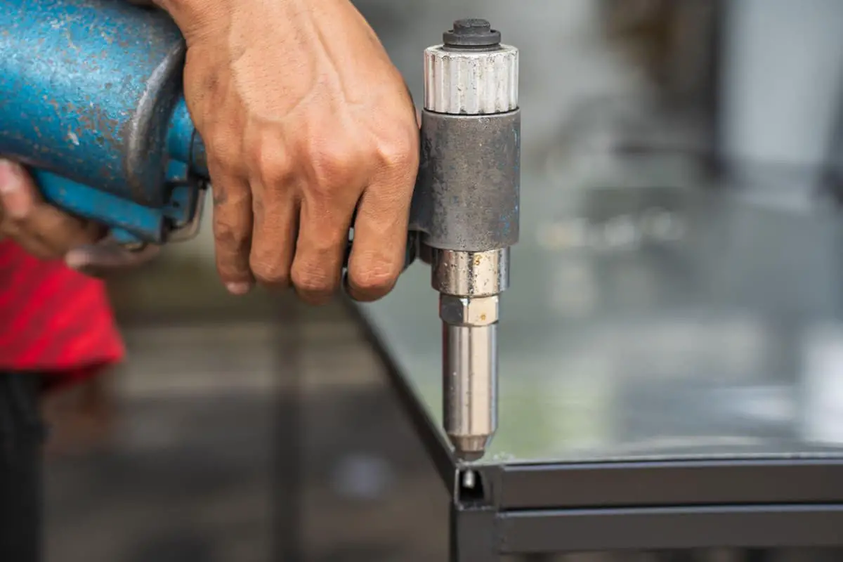
(1) Riveting
Riveting is a method in which two plates are joined together using a type of rivet known as a pull rivet. Common riveting shapes are illustrated in the following figure:
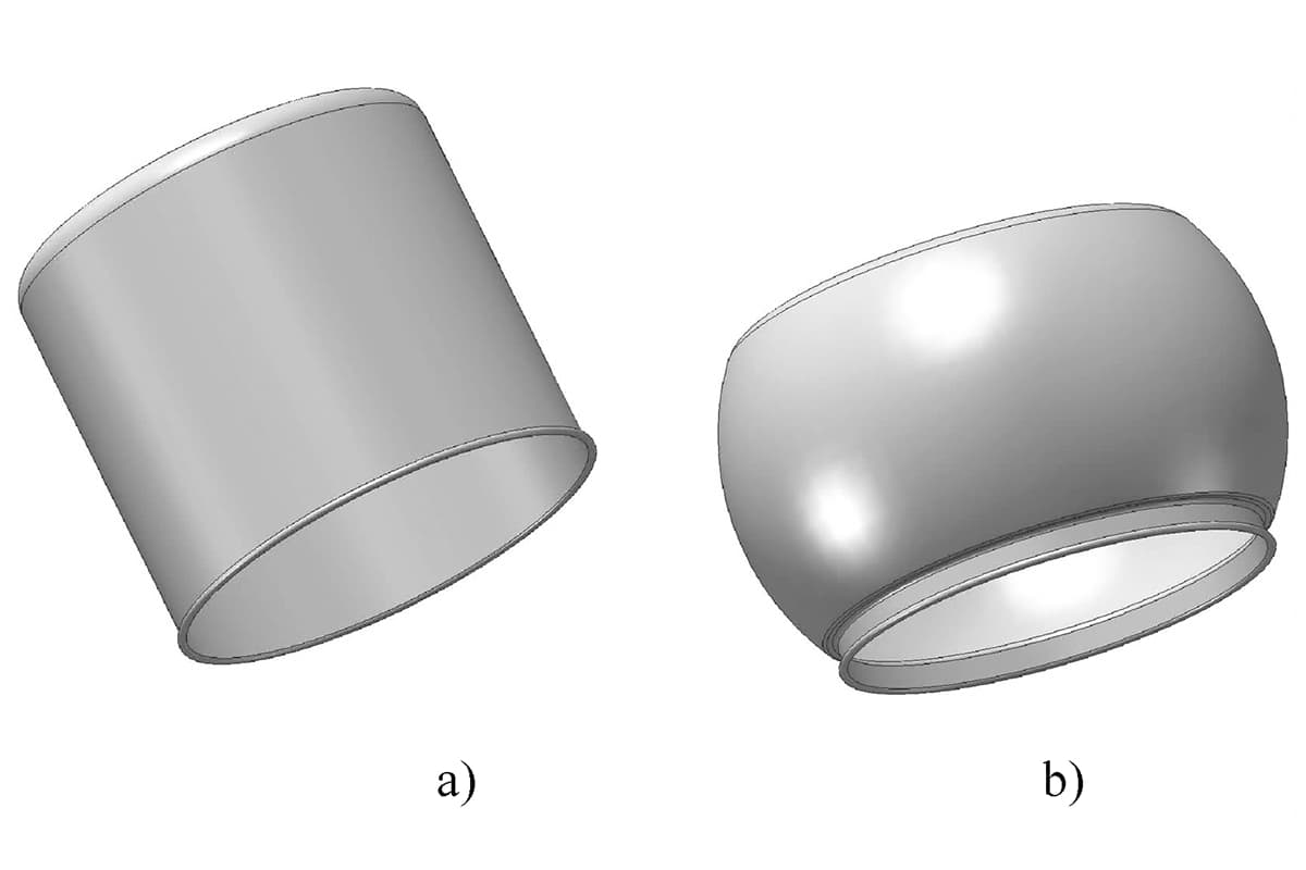
(2) Pull-Out Riveting:
One part is a drawn hole while the other is a counterbore, which is transformed into a permanent connection through riveting die.
Advantages: The hole itself provides a positioning function. The riveting strength is high and the efficiency of riveting through the die is also high.
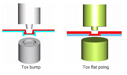
(3) Tox Riveting:
The connected part is pressed into the die through a simple punch. Under further pressure, the material in the die flows outward, creating a round connection point without sharp edges or burrs and preserving its corrosion resistance. The coating or spray coating on the surface of the plate is also deformed and flowed together, retaining its original anti-rust and anti-corrosion properties.
The material is pushed to both sides and into the panel near the die side to form the Tox connection dot, as shown in the following figure:
5. Surface treatment
The surface treatment of sheet metal serves both the purpose of anti-corrosion protection and decoration. Common surface treatments include powder spraying, electro-galvanizing, hot-dip galvanizing, surface oxidation, surface drawing, and silk screen printing. Before undergoing surface treatment, it is important to remove any oil stains, rust, and welding slag from the surface of the sheet metal.
(1) Powder Spraying: There are two options for surface paint on sheet metal – liquid paint and powder paint. The latter is more commonly used. Powder spraying involves electrostatically adsorbing and high-temperature baking a layer of various colored coatings onto the surface of the sheet metal, enhancing both its appearance and anti-corrosion performance.
(2) Electro-galvanizing and Hot-dip Galvanizing: Galvanizing the surface of sheet metal is a popular anti-corrosion treatment method that also improves its appearance. There are two forms of galvanizing – electro-galvanizing and hot-dip galvanizing. Electro-galvanizing produces a bright, flat appearance with a thin zinc coating, while hot-dip galvanizing results in a thicker zinc coating that creates a zinc-iron alloy layer, offering stronger corrosion resistance than electro-galvanizing.
(3) Surface Oxidation: This section focuses on the surface anodization of aluminum and aluminum alloys. Surface anodization can produce a variety of colors and provide both protective and decorative effects. The process also creates an anodic oxide film on the surface of the material, which boasts high hardness, wear resistance, and good electrical and thermal insulation properties.
(4) Surface Drawing: The material is placed between the upper and lower rollers of a wire drawing machine, with an abrasive belt attached to the rollers. The material is then driven through the abrasive belts, producing traces on its surface. The thickness of the traces depends on the type of abrasive belt used, and the main purpose of this treatment is to enhance the appearance of the material. This surface treatment method is typically only considered for aluminum.
(5) Silk Screen Printing: Screen printing on materials can be divided into flat screen printing and pad printing. Flat screen printing is used on flat surfaces, while pad printing is used on surfaces with deep pits. Silk screen printing requires a silk impression.
As the founder of MachineMFG, I have dedicated over a decade of my career to the metalworking industry. My extensive experience has allowed me to become an expert in the fields of sheet metal fabrication, machining, mechanical engineering, and machine tools for metals. I am constantly thinking, reading, and writing about these subjects, constantly striving to stay at the forefront of my field. Let my knowledge and expertise be an asset to your business.
Have you ever wondered how metal can be shaped into intricate forms with precision and efficiency? This article dives into the fascinating world of metal expansion methods, explaining various techniques…
Have you ever wondered how sheet metal parts are joined together to create complex structures? In this blog post, we'll explore the fascinating world of sheet metal joining techniques. As…
How do you ensure the reliability of sheet metal connections in your projects? Understanding the various methods of threaded connections and riveting is essential. This article delves into the principles…
Imagine transforming the design and manufacturing of sheet metal parts from a cumbersome, error-prone process into a seamless, efficient operation. This article delves into the powerful role of CAD/CAM technology…
Have you ever wondered how everyday objects stay together? From the plastic toys we play with to the sturdy metal bridges we cross, joining techniques are at work. In this…
In this blog post, we'll dive into the intriguing terminology and techniques used in this essential manufacturing field. Our expert mechanical engineer will guide you through the key concepts, providing…
1. Cold Bending Forming Technology Cold bending forming technology is a continuous localized cold processing method, which involves applying external force to the metal at the bend angle through multiple…
Imagine a production line that not only boosts efficiency but also slashes costs and enhances safety. The automated steel door frame production line achieves just that by integrating advanced robotics…
Why is straightening parts in sheet metal fabrication so crucial? Imagine a car with wobbly wheels. Similarly, uneven metal parts can lead to inefficiencies and defects in production. This article…