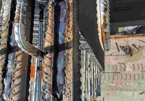
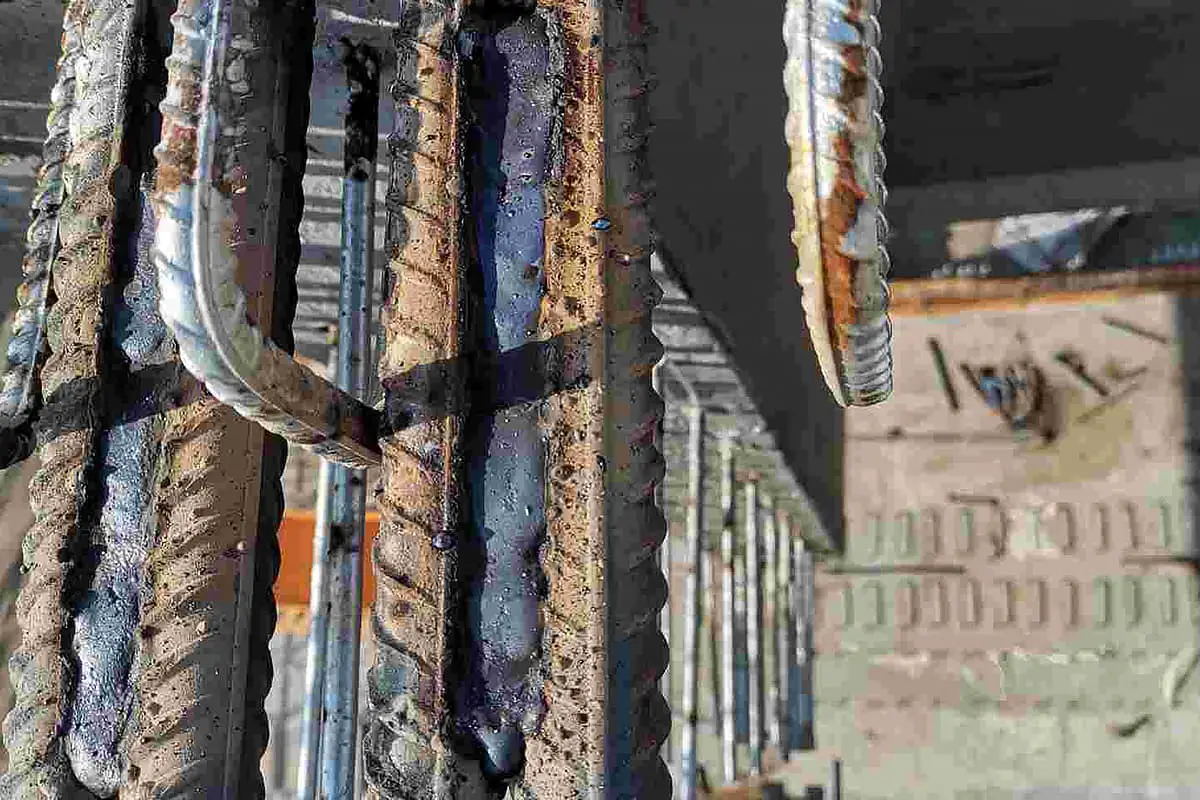
Reinforced construction is a critical process in engineering construction. It usually involves procedures such as reinforcement fabrication, binding and installation, and welding.
Among these procedures, the quality of welding has a direct impact on the quality of reinforced construction.
1. Appearance Defects
Appearance defects (surface defects) refer to defects that can be detected from the surface of a workpiece without relying on instruments.
Common appearance defects include undercut, weld tumor, depression, welding distortion, sometimes, surface porosity and surface cracks, and incompletely penetrated root in single-sided welding.
A. Undercut
It refers to a groove or groove formed in the base metal part along the weld toe. It is caused by insufficient filling of the molten metal to the edge of the weld seam after the arc melts the edge of the weld seam.
The main causes of undercut:
The high arc heat, i.e., too much current and too slow welding speed, result in undercut. Incorrect angle between electrode and workpiece, unreasonable swing, arc too long and unreasonable welding sequence can all cause undercut.
The arc blow of DC welding is also a reason causing undercut. Some welding positions (vertical, horizontal, and overhead) will exacerbate undercut.
Undercut reduces the effective cross-sectional area of the base metal, reduces the load-carrying capacity of the structure, and also causes stress concentration, leading to crack sources.
Prevention of undercut:
Correcting the operation posture, selecting appropriate standards, and adopting a proper welding approach can eliminate undercut.
Using AC welding instead of DC welding can effectively prevent undercut when welding angled welds.
B. Weld tumor
The liquid metal in the weld flows onto the insufficiently heated base metal that is not melted, or overflows from the root of the weld, forming an unmelted metal tumor after cooling, which is called a weld tumor.
Strong welding specifications, too fast melting of the electrode, poor quality of the electrode (such as off-centering), unstable welding power supply characteristics, and incorrect operation posture are prone to cause weld tumors.
Weld tumors are more likely to form in horizontal, vertical, and overhead positions.
Weld tumors are often accompanied by incomplete fusion and slag inclusion defects, which can cause cracks.
At the same time, weld tumors change the actual size of the weld and cause stress concentration. The weld tumor inside the pipe decreases its inner diameter and may cause blockages in the flow of fluid.
Measures to prevent weld tumors:
Keep the weld flat during welding, correctly select the specification, choose an off-center-free electrode, and operate reasonably.
C. Pitting
Pitting refers to the part of the weld surface or back that is lower than the base metal.
Pitting is mostly caused by the electrode (welding wire) failing to stop for a short time when the arc is terminated (the resulting pitting is called an arc pit). When welding in the overhead, vertical, and horizontal positions, internal pitting often occurs at the root of the weld on the backside.
Pitting reduces the effective cross-sectional area of the weld, and arc pits usually have arc pits cracks and arc pit shrinkage cavities.
Measures to prevent pitting:
Use a welding machine with a current decay system, choose a flat welding position as much as possible, select suitable welding specifications, and let the electrode stay in the molten pool for a short time or swing circularly when the arc is terminated to fill the arc pit.
D. Incomplete penetration
Incomplete penetration refers to continuous or intermittent grooves on the surface of the weld. Insufficient filling metal is the root cause of incomplete penetration.
Weak welding specifications, too thin electrode, and improper operation can result in incomplete penetration.
Incomplete penetration also weakens the weld, making it prone to stress concentration. At the same time, weak welding specifications increase the cooling rate, which can lead to porosity, cracks, and other defects.
Measures to prevent incomplete penetration:
Increase welding current and add cover pass welds.
E. Burn through
Burn through refers to the defect that occurs during welding, in which the melting depth exceeds the thickness of the workpiece, and the molten metal flows out from the back of the weld, forming a perforated defect.
Too high welding current, too slow speed, and arc dwell at the weld will all cause burn-through defects. The gap between the workpieces is too large, and the bevel is too small, which is also prone to burn-through.
Burn-through is not allowed on boiler pressure vessel products; it completely destroys the weld, causing the joint to lose its connection and load-carrying capacity.
Prevention and control measures:
Use a smaller current and appropriate welding speed, reduce the assembly gap, add a backing or plug on the back of the weld. Using pulse welding can effectively prevent burn-through.
F. Other surface defects
(1) Poor forming
The appearance and geometric dimensions of the weld do not meet the requirements. There are welds that are too high, have an uneven surface, and the weld is too wide or transitions poorly to the base material.
(2) Misalignment
Two workpieces are shifted from each other in the thickness direction, which can be seen as both a surface defect of the weld and an assembly forming defect.
(3) Collapse
In single-sided welding, due to excessive input heat and too much melting metal, the liquid metal collapses to the back of the weld, and the back of the weld protrudes after forming, while the front collapses.
(4) Surface porosity and shrinkage cavities
(5) Various welding deformations such as angular deformation, twisting, wave deformation, etc. are also welding defects. Angular deformation is also an assembly forming defect.
2. Porosity and Slag Inclusions
A. Porosity
Porosity refers to the cavities formed in the weld due to the gas in the molten pool that did not escape before the metal solidified.
The gas may be absorbed by the molten pool from the external environment or generated during the welding metallurgical process.
1. Classification of porosity
According to its shape, porosity can be classified into spherical porosity and worm-shaped porosity.
According to the number of pores, it can be divided into single pores and clustered pores. Clustered pores include uniformly distributed pores, densely distributed pores, and linearly distributed pores.
According to the composition of the gas inside the pore, there are hydrogen pores, nitrogen pores, carbon dioxide pores, carbon monoxide pores, oxygen pores, etc. The pores generated during fusion welding are mainly hydrogen pores and carbon monoxide pores.
2. Mechanisms for porosity formation
The solubility of gas in solid-state metal at room temperature is only one-tenth to one-hundredth of that in liquid state metal at high temperature.
When the molten pool metal solidifies, a large amount of gas needs to escape from the metal. When the solidification rate is greater than the rate at which gas escapes, porosity is formed.
3. Main causes of porosity
Rust and oil stains on the surface of the base metal or filling metal, and the welding rod or flux not being dried can increase the amount of pores in the weld because the moisture in rust, oil stains, and the coating of the welding rod and flux decomposes into gas at high temperatures, increasing the gas content in the molten metal.
When the welding energy is too low, the cooling rate of the molten pool is too high, which is not conducive to the escape of gas. Insufficient deoxidation of the weld metal can also increase oxygen pores.
4. Hazards of porosity
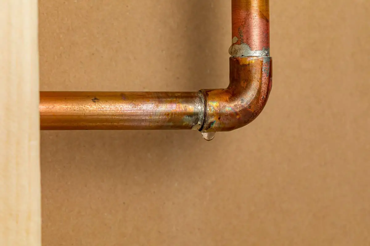
Porosity reduces the effective cross-sectional area of the weld, making the weld loose, thereby reducing the joint’s strength and plasticity. It can also cause leaks.
Porosity is also a factor that causes stress concentration. Hydrogen pores may promote cold cracking.
5. Measures to prevent porosity
❶ Clean the oil, rust, moisture, and debris on the surface of the welding wire, the working groove, and its vicinity.
❷ Use alkaline welding rods and flux and thoroughly dry them.
❸ Weld using direct current reverse polarity and a short arc.
❹ Preheat before welding to slow down the cooling rate.
❺ Use a slightly stronger specification for welding.
B. Slag inclusions
Slag inclusion refers to the phenomenon of residual slag remaining in the weld seam after welding.
1. Classification of Slag Inclusions
❶ Metallic Slag Inclusion: Refers to the residual metal particles such as tungsten or copper in the weld seam, commonly known as tungsten inclusion or copper inclusion.
❷ Non-metallic Slag Inclusion: Refers to the residue of unmelted flux coating or flux, sulfides, oxides, nitrides in the weld seam. If the metallurgical reaction is incomplete, slag removal is difficult.
2. Distribution and Shape of Slag Inclusions
There are single-point slag inclusions, linear slag inclusions, chain-shaped slag inclusions, and dense slag inclusions.
3. Causes of Slag Inclusions
- Inappropriate groove size;
- Impurities in the groove;
- Incomplete slag removal between layers in multi-layer welding;
- Low welding line energy;
- Rapid cooling of the weld seam, resulting in the metal solidifying too quickly;
- Flux coating or flux composition of the welding rod is not reasonable, with a high melting point;
- During tungsten inert gas welding, improper polarity of the power supply, high current and current density, and tungsten electrode melting and falling off into the molten pool;
- Poor welding rod swing during manual welding, unfavorable for slag floating.
Corresponding measures should be taken to prevent slag inclusion based on the above reasons.
4. The Harm of Slag Inclusions
The harm of point slag inclusions is similar to that of pores. Slag inclusions with a sharp end will generate stress concentration, and the sharp end will also develop into a crack source, which is more harmful.
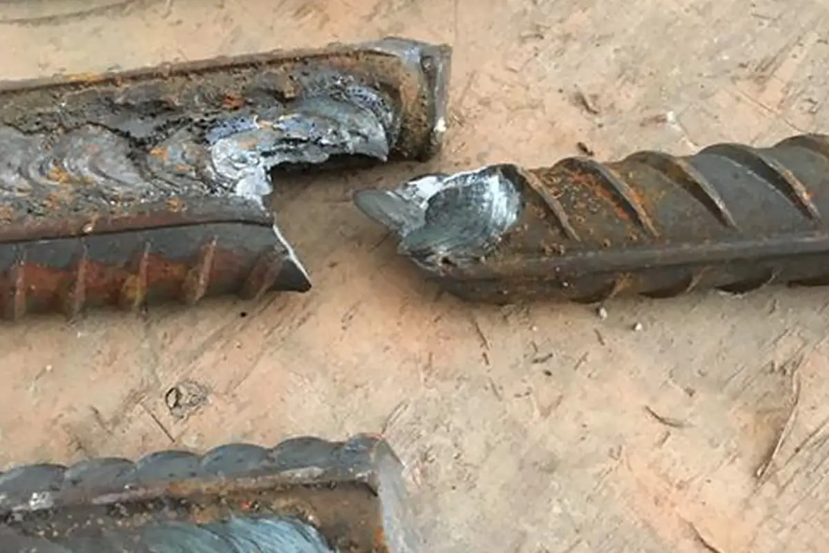
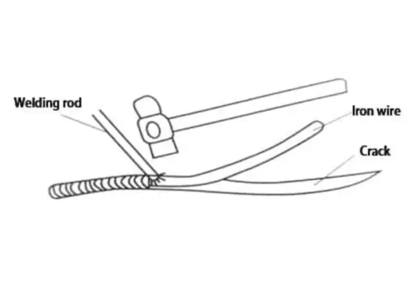
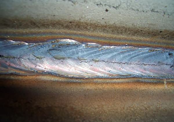
3. Cracks
The breaking of the atomic bond in the weld seam, resulting in a new interface and a gap, is called a crack.
A. Classification of Cracks
According to the size of the crack, it can be divided into three types:
(1) Macroscopic cracks: cracks visible to the naked eye.
(2) Microcracks: can only be detected under a microscope.
(3) Ultra-micro cracks: can only be detected under a high-power microscope, generally referring to intergranular cracks and intracrystalline cracks.
From the perspective of the production temperature, cracks can be divided into two categories:
(1) Hot cracks: cracks produced near the Ac3 line. They generally appear immediately after welding and are also called solidification cracks. This type of crack mainly occurs at grain boundaries, and there is an oxidized color on the crack surface, which loses its metallic luster.
(2) Cold cracks: refers to the cracks produced when cooled below the martensite transformation temperature M3 after welding, which generally appear after a period of time after welding (several hours, several days, or even longer). Therefore, they are also called delayed cracks.
According to the reasons for the generation of cracks, cracks can be divided into:
(1) Reheat cracks: cracks produced when the joint is reheated to 500~700℃ after cooling. Reheat cracks occur in the coarse-grained region of the weld heat-affected zone of precipitation-strengthened materials (such as metals containing Cr, Mo, V, Ti, Nb), and generally develop from the fusion line to the coarse-grained region of the heat-affected zone, showing intergranular cracking characteristics.
(2) Laminar tearing is mainly due to the inclusion of impurities such as sulfides (MnS) and silicates in the steel during the rolling process, forming anisotropy. Under welding stress or external restraint stress, the metal cracks along the direction of rolling impurities.
(3) Stress corrosion cracking: cracks produced under the combined action of stress and corrosive medium. In addition to residual stress or confinement stress factors, stress corrosion cracking is mainly related to the structure and morphology of the weld.
B. Hazards of Cracks
Especially for cold cracks, the harm is catastrophic. Most of the pressure vessel accidents in the world are caused by brittle fracture caused by cracks, except for a few cases caused by unreasonable design or improper material selection.
Hot cracks (solidification cracks)
(1) Formation mechanism of solidification cracks
Hot cracks occur during the late solidification stage of the weld metal, and the sensitive temperature range is generally in the high-temperature zone near the solid phase line.
The most common hot crack is a solidification crack, which is formed when impurities that generate low-melting-point eutectics are enriched at the grain boundary due to crystallization segregation during the solidification process of the weld metal, forming a so-called “liquid film.”
In a specific sensitive temperature range (also known as the brittle temperature range), its strength is very small, and it will crack due to tensile stress caused by weld solidification shrinkage, eventually forming a crack. Solidification cracks most commonly occur longitudinally along the center length of the weld and are called longitudinal cracks.
Sometimes they also occur between two columnar crystals inside the weld, called transverse cracks. Arc pit cracks are another form of solidification cracks and are common hot cracks.
Hot cracks usually occur along the grain boundaries and typically occur in gas welding joints of materials with many impurities, such as carbon steel, low-alloy steel, and austenitic stainless steel.
(2) Factors affecting solidification cracks
❶ The influence of alloy elements and impurities: The increase in carbon elements and impurity elements such as sulfur and phosphorus will enlarge the sensitive temperature range and increase the opportunity for solidification cracks.
❷ The influence of cooling rate: Increasing the cooling rate will increase the degree of crystallization segregation and broaden the crystallization temperature range, both of which will increase the chance of solidification cracks.
❸ The influence of crystallization stress and restraint stress: In the brittle temperature range, the strength of the metal is extremely low, and welding stress makes some metal parts subject to tensile stress. When the tensile stress reaches a certain level, solidification cracks will occur.
(3) Measures to prevent solidification cracks
❶ Reduce the content of harmful elements such as sulfur and phosphorus and use materials with lower carbon content for welding.
❷ Add a certain amount of alloy elements to reduce columnar crystals and segregation. Elements such as aluminum, zirconium, iron, and molybdenum can refine the grain size.
❸ Use a weld with a shallow melting depth to improve the heat dissipation conditions, causing low-melting-point substances to float on the surface of the weld and not exist within the weld.
❹ Reasonably select welding specifications and adopt preheating and post-heating to reduce the cooling rate.
❺ Adopt a reasonable assembly sequence to reduce welding stress.
Reheat cracks
(1) Characteristics of reheat cracks
❶ Reheat cracks occur in the over-heated coarse-grained areas of the weld heat-affected zone. They occur during the process of re-heating such as post-weld heat treatment.
❷ The production temperature range of reheat cracks: Carbon steel and alloy steel 550~650℃; austenitic stainless steel ~300℃.
❸ Reheat cracks are intragranular cracks (along the grain boundary).
❹ They are most likely to occur in precipitation-hardened steels.
❺ Associated with residual welding stress.
(2) Mechanisms of reheat cracks
There are several explanations for the mechanism of reheat cracks, and the explanation of the model fracture theory is as follows: In the near-weld area, under the action of high-temperature thermal cycling, strengthened-phase carbides (such as iron carbide, carbide, chromium carbide, and misplaced carbide) are deposited on the dislocation area within the crystal, making the internal strengthening strength much higher than the intergranular strengthening strength.
Especially when the strengthened phase is uniformly distributed within the grain, it hinders the local adjustment of the inside of the grain and also hinders the overall deformation of the grain.
Thus, the plastic deformation caused by stress relaxation is mainly borne by the metal at the grain boundary, so the stress at the grain boundary is concentrated, and crack occurs, which is called model fracture.
(3) Prevention of reheat cracks
❶ Pay attention to the strengthening effect of metallurgical elements and their effects on reheat cracks.
❷ Reasonable preheating or adopting post heating to control the cooling rate.
❸ Reduce residual stress to avoid stress concentration.
❹ During tempering treatment, try to avoid the sensitive temperature range of reheat cracks or shorten the dwell time within this temperature range.
Cold Cracks
(1) Characteristics of cold cracks
❶ Cold cracks occur at lower temperatures and after a period of time after welding, so they are also called delayed cracks.
❷ They mainly occur in the heat-affected zone and can also occur in the weld zone.
❸ Cold cracks may be intergranular cracks, transgranular cracks, or a mixture of the two.
❹ The failure of components caused by cold cracks is a typical brittle fracture.
(2) Mechanisms of cold cracks
❶ The hardened structure (martensite) reduces the plastic reserves of the metal.
❷ The residual stress of the joint causes the weld to be pulled.
❸ There is a certain amount of hydrogen in the joint.
Hydrogen content and tensile stress are two important factors in the formation of cold cracks (here, referring to hydrogen-induced cracks).
Generally, the arrangement of atoms inside metals is not completely ordered but contains many microscopic defects. Under the action of tensile stress, hydrogen diffuses and accumulates in the high-stress area (defect area). When the hydrogen concentration reaches a certain level, it will break the bonding between atoms in the metal, resulting in some microscopic cracks.
Under the continuous action of stress, hydrogen continuously accumulates, microscopic cracks continuously expand, until it develops into macroscopic cracks, and eventually breaks. The critical hydrogen concentration and critical stress value determine the occurrence of cold cracks.
When the hydrogen concentration inside the joint is less than the critical hydrogen concentration, or the stress applied is less than the critical stress, cold cracks will not occur (that is, the delay time is infinitely long). Among all cracks, cold cracks are the most harmful.
(3) Measures to prevent cold cracks
❶ Use low-hydrogen alkaline electrodes, strictly dry and store them at 100-150°C, and use them as soon as possible after taking them out.
❷ Increase the preheating temperature, adopt post-heating measures, ensure that the interlayer temperature is not lower than the preheating temperature, choose reasonable welding specifications, and avoid the formation of hardened structures in the weld.
❸ Choose a reasonable welding sequence to reduce welding deformation and welding stress.
❹ Carry out timely dehydrogenation heat treatment after welding.
4. Incomplete Penetration
Incomplete penetration refers to the phenomenon that the base metal is not melted and the weld metal does not enter the root of the joint.
1. Reasons for incomplete penetration
(1) Low welding current and shallow penetration depth.
(2) Improper groove and gap size, too large blunt edge.
(3) The influence of magnetic blow.
(4) Excessive electrode eccentricity.
(5) Poor cleaning of the interlayer and the weld root.
2. Hazards of incomplete penetration
One of the hazards of incomplete penetration is that it reduces the effective cross-sectional area of the weld and decreases the joint strength.
Moreover, the harm caused by stress concentration due to incomplete penetration is much greater than the harm caused by strength reduction. Incomplete penetration seriously reduces the fatigue strength of the weld.
Incomplete penetration may become a source of cracks, which is an important cause of weld failure.
The harm caused by stress concentration due to incomplete penetration is much greater than the harm caused by strength reduction. Incomplete penetration seriously reduces the fatigue strength of the weld.
3. Prevention of incomplete penetration
Using larger welding current is a basic method to prevent incomplete penetration. In addition, when welding angle joints, using AC instead of DC to prevent magnetic blow, reasonably designing grooves and strengthening cleaning, and using short arc welding measures can also effectively prevent incomplete penetration.
5. Lack of Fusion
Lack of fusion refers to the defect that the weld metal and the base metal, or the weld metal and the weld metal, are not fused together.
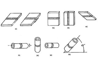
According to its location, lack of fusion can be divided into three types: lack of fusion in the groove, lack of fusion between layers, and lack of fusion at the root.
1. Reasons for lack of fusion defects
(1) Welding current is too low.
(2) Welding speed is too fast.
(3) The angle of the electrode is not correct.
(4) Arc blow phenomenon occurs.
(5) The welding is in a downhill position, and the base metal that has not been melted has been covered by molten iron.
(6) The surface of the base metal is affected by pollutants or oxides, which affect the fusion bonding between the deposited metal and the base metal.
2. Hazards of lack of fusion
Lack of fusion is an area-type defect. Lack of fusion at the groove and lack of fusion at the root both significantly reduce the carrying cross-sectional area and cause severe stress concentration. Its harmfulness is second only to that of cracks.
3. Prevention of lack of fusion
Using a larger welding current, correctly performing the welding operation, and paying attention to the cleanliness of the groove are effective measures to prevent lack of fusion.
6. Other Defects
(1) The chemical composition or microstructure of the welded joint does not meet the requirements:
Improper matching of the welding material and the base metal, or the burning of elements during the welding process, can easily cause changes in the chemical composition of the weld metal or result in a microstructure that does not meet the requirements.
This may lead to a decrease in the mechanical properties of the welded joint and also affect the corrosion resistance performance of the joint.
(2) Overheating and burning:
If welding specifications are used improperly, the heat-affected area will stay at a high temperature for a long time, which can cause the grain to become coarse, resulting in overheated microstructures.
If the temperature further rises and the duration is prolonged, it may cause oxidation or local melting of the grain boundaries, resulting in burned microstructures.
Overheating can be eliminated by heat treatment, while burning is an irreversible defect.
(3) Underbead cracking:
Cracks that form in the base metal adjacent to the weld metal or in the heat-affected zone; caused by welding stresses and strains combined with the restrained dissimilar expansion and contraction rates.
Steel welding technology includes various types, and to strengthen the quality control of construction, the reasonable application of steel welding technology should be based on the specific conditions of the engineering project, to ensure the stability and safety of the entire building structure.
Therefore, it is important for everyone to pay attention to the above steel welding defects during construction.